background image

Chapter 2: Activating the Modem

28

BlueTree Wireless BT-2010 Product Manual

V1.5

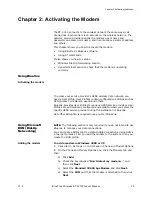
AT+ICF=<format>[,<parity>]
OK

Sets the serial DTE-DCE character 
framing.

<format>
0: auto-detect
1: 8 Data 0 Parity 2 Stop
2: 8 Data 1 Parity 1 Stop
3: 8 Data 0 Parity 1 Stop
4: 7 Data 0 Parity 2 Stop
5: 7 Data 1 Parity 1 Stop
6: 7 Data 0 Parity 1 Stop

<parity>
0: Odd
1: Even
2: Mark
3: Space
4: None

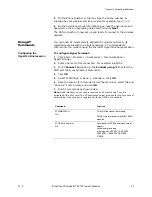
AT+CPIN?
+CPIN: READY

Checks the SIM card 

AT+CREG?
+CREG: 0,1
OK

Checks that the modem is registered on 
the network. A response of +CREG: 1,1 
indicates that the modem is registered 
with the network.

AT+FCLASS=0
OK

Puts in data mode

AT+CGDCONT=1,"IP","apn","0.0.0.0",0,0
OK

Establishes the PDP context. Note that 
there are no spaces in the string.

AT+CGQREQ=1,0,0,0,0,0
OK

Requested quality of service profile

AT+CGQMIN=1,0,0,0,0,0
OK

Minimum quality of service profile

AT+WGPRS=0,0
OK

Sets modems for automatic attachment.

For Wavecom 2426 modules only.

AT+CGACT=1,1
OK

Activates PDP context

AT+CGATT?
+CGATT: 1
OK

Verifies that the modem is GPRS 
attached. If the +CGATT: value is not 1, 
type AT+CGATT=1 and wait for the 
connection to be established. 

Command

Function

Summary of Contents for BT-2000

Page 1: ...BT 2010 GPRS Standard GPS Modem Product Manual ...

Page 2: ......

Page 3: ...V1 5 BlueTree Wireless BT 2010 Product Manual 3 BlueTree Wireless BT 2010 GPRS Standard GPS Modem Product Manual July 2004 GPRSUG 02010 ...

Page 4: ...4 BlueTree Wireless BT 2010 Product Manual V1 5 ...

Page 5: ...a H8T 3C9 Tel 1 514 422 9110 Toll Free 1 877 422 9110 www bluetreewireless com Copyright 2004 by BlueTree Wireless Data Inc All Rights Reserved Printed in Canada BlueTree the BlueTree logo and BlueVue are trademarks of BlueTree Wireless Data Inc All other trademarks are the property of their respective owners ...

Page 6: ...y energy and if not installed and used in accordance with the manufacturer s instructions may cause interference harmful to radio communications However there is no guarantee that interference will not occur in a particular installation If this equipment does cause harmful interference to radio or television reception which can be determined by turning the equipment off and on the user is encourag...

Page 7: ... BT 2010 modem in areas near medical equipment where blasting is in progress where explosive atmospheres may be present or near any equipment that may be susceptible to any form of radio interference Warning Antenna must not exceed 5 15 dBi This device must be used in mobile configurations The antenna s used for this transmitter must be installed to provide a separation distance of at least 30 cm ...

Page 8: ...8 BlueTree Wireless BT 2010 Product Manual V1 5 ...

Page 9: ... 21 Installing the BlueVue software 21 Chapter 2 Activating the Modem Using BlueVue 25 Using Microsoft DUN Dial Up Networking 25 Using AT Commands 27 Chapter 3 Connecting to the Wireless Network Using BlueVue 31 Using Microsoft DUN Dial Up Networking 32 Chapter 4 Using the GPS Features GPS Features Overview 33 Power Up and Initialization 33 Using BlueVue 34 Tracking GPS location 35 Chapter 5 Troub...

Page 10: ...e Information Modem Reference 45 BlueVue Configuration Options 46 BlueVue Basics 49 Microsoft DUN Dial Up Networking 59 AT Commands 60 GPS Reference 65 Appendix C Modem Specifications Physical Dimensions 69 Product Specifications 71 Power Consumption 72 Certification 72 ...

Page 11: ...nstallations The modem is based on RIM s 1902G or Wavecom s Q2426 radio module and intended for use with a host platform such as a computer or remote terminal data unit The modem provides Compatibility with GSM and GPRS wireless services Support for 850 and 1900 MHz frequency bands Short Message Service functionality for both mobile originate as well as terminate messaging GPS location capability ...

Page 12: ...izontal metal surface of vehicle Protocol Description TSIP Trimble Standard Interface Protocol Binary bidirectional Default protocol of GPS receiver TAIP Trimble ASCII Interface Protocol Uses printable character based sentences NMEA 0183 National Marine Electronics Association Protocol ASCII character based Unidirectional from receiver only Warning Antenna must not exceed 5 15 dBi This device must...

Page 13: ...ial adapters BlueTree has tested USB Serial adapter solutions from FTDI http www ftdichip com that have worked properly with our modems Single USB Serial adapters and USB Dual Serial adapters have been tested and work properly More product information can be found at FTDI distributors websites http www ftdichip com FTDisti htm Checking for port conflicts If you are connecting the modem to a PC con...

Page 14: ...Introduction 14 BlueTree Wireless BT 2010 Product Manual V1 5 ...

Page 15: ...oot power cable with 2A inline fuse Quick Start Guide BlueTree installation CD includes the Product Manual along with BlueVue software BlueVue software is available from our web site at http www bluetreewireless com If any items from this list are missing please call our service department toll free at 1 877 422 9110 Installing the SIM Card Note Before inserting the SIM card be sure the power cabl...

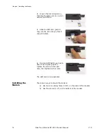
Page 16: ...s of the modem b Use the din rail 1 4 on the bottom of the modem 2 Loosen the remaining screw then flip the plate over so you can access the SIM slot 3 Slide the SIM card gold on top into the slot until you feel it snap into place 4 Flip the SIM CARD cover plate back to its original position replace the screw in the open hole then tighten both screws The SIM card is now installed ...

Page 17: ...ppropriate cable type and length To install the cellular band antenna 1 Thread the antenna cable through the vehicle so the cable can reach the front plate of the modem 2 Connect the cable to the TNC connector finger tight Do not use tools Warning Antenna must not exceed 5 15 dBi This device must be used in mobile configurations The antenna s used for this transmitter must be installed to provide ...

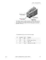
Page 18: ... antenna must be located outdoors with an unobstructed view of the sky To install the GPS antenna 1 Thread the antenna cable through the vehicle so the cable can reach the front plate of the modem 2 Connect the cable to the SMA connector Installing the Power Cable The modem includes a 15 foot power cable with 2A inline fuse Power cable connector As shown below the power cable connects to the modem...

Page 19: ...ill turn on when the ignition sense line is set between 8 and 30 volts DC The modem will turn off if the ignition sense line is less than 7 volts DC Pin designations for the connector are shown below Pin Annotation Color Description 1 GND Black Ground 2 POS Red Power supply input to 30 Vdc 3 IGN White Ignition input 4 OUT Green Digital output not connected ...

Page 20: ...ing on and off the modem b the vehicle s Accessory for position 2 for turning ON the modem without turning on the engine c the vehicle s Accessory for position 3 for turning ON the modem only when the engine is turned on To test the power connection 1 Check the modem s LED indicators If the PWR or Power indicator is turned on or if it flashes the modem is powered If the PWR or Power indicator is n...

Page 21: ...ial cable to an available COM port To connect the GPS data cable 1 Attach one end of the second serial cable to the modem on the connector labeled AUX 2 Attach the other end to an available COM port on the computer Installing the BlueVue software BlueVue is BlueTree s modem management software that makes configuring and operating your modem simple and quick Your modem includes a BlueVue installati...

Page 22: ...elect Your Configuration screen in the Please select your model number list select your modem If you don t know the model number of the modem you can find it on the product label located on the bottom of the modem 6 Select the wireless service provider that you have an account with from the list box and then click Next 7 On the COM Port Selection screen in the Select Primary Data COM Port list sel...

Page 23: ... as part of the submission for Windows certification 12 On the Hardware Installation warning screen click Continue Anyway Again BlueTree has done extensive testing of the software to ensure its reliability and as part of the submission for Windows certification 13 On the BlueTree Installation Wizard Complete screen select Launch the program if you want the installation wizard to start the applicat...

Page 24: ...Chapter 1 Installing the Modem 24 BlueTree Wireless BT 2010 Product Manual V1 5 This page intentionally left blank ...

Page 25: ...ccess Point Name userid and others BlueVue provides User Profiles for various GPRS service providers User Profiles are automatically configured and available when you select the specific GPRS service provider during the installation of BlueVue No further activation is required once you start BlueVue Using Microsoft DUN Dial Up Networking NOTE The following section is only required if you do not in...

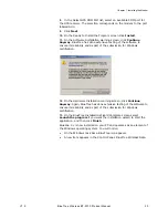
Page 26: ...en click Next 4 On the Getting Ready box select Set up my connection manually and then click Next 5 On the Internet Connection box select Connect to a dialup modem and then click Next 6 On the Select a Device box select the 33600bps modem and then click Next 7 On the Connection Name box type in a name for the connection for example GPRS and then click Next String element Function AT D2 Sets the mo...

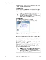
Page 27: ...lick Start Programs Accessories Communications HyperTerminal 2 Enter a name for this connection For example BlueTree 3 In the Connect to window in the Connect using field select the COM port that your modem is attached to 4 Click OK 5 Select 115200bps 8 None 1 Hardware Click OK 6 Save the session for future use From the menu bar select File and Save As Enter a name and click OK 7 Run AT commands a...

Page 28: ...tered on the network A response of CREG 1 1 indicates that the modem is registered with the network AT FCLASS 0 OK Puts in data mode AT CGDCONT 1 IP apn 0 0 0 0 0 0 OK Establishes the PDP context Note that there are no spaces in the string AT CGQREQ 1 0 0 0 0 0 OK Requested quality of service profile AT CGQMIN 1 0 0 0 0 0 OK Minimum quality of service profile AT WGPRS 0 0 OK Sets modems for automa...

Page 29: ... a usable signal If the value is lower than 10 move the antenna or the modem to a location where you know the signal quality is strong An RSSI value of 99 indicates no signal AT RCIQ OK Checks cell parameter information If the device is not registered with the network when a query is made the user is notified that the radio modem has not yet been registered with the network RIM 1902G module only C...

Page 30: ...Chapter 2 Activating the Modem 30 BlueTree Wireless BT 2010 Product Manual V1 5 ...

Page 31: ...nnect to the wireless network Manually 1 From the Profiles list select a connection profile In a few moments the modem status field will display the globe symbol The lower right area displays the connection statistics for your wireless session You are now connected to the wireless network Auto Connect and Auto Reconnect If the Auto Connect Enable box is checked then BlueVue will automatically esta...

Page 32: ...p From the Start menu To connect to the wireless network 1 Click Start Settings Control Panel Network Connections 2 In the Network Connections directory under Dial Up double click the icon of the GPRS connection or the name you chose earlier You are now connected to the wireless network You will see the connection icon on the Windows task bar From the My Network Places icon To connect to the wirel...

Page 33: ...ormation please see GPS Reference on page 65 Power Up and Initialization Although the GPS receiver functions independently from the data modem it does run on the same power supply so it powers up at the same time as the modem The module does need to be fully initialized to function properly Initializing the GPS receiver the first time To initialize the GPS receiver 1 Power up the modem 2 Do not po...

Page 34: ...4 In the COM Port list select the COM port on the PC that will be attached to the GPS port AUX on the modem 5 In the Units of Measurement list select the appropriate units in which to display the GPS data The table below describes the options 6 The GPS manager can be selected to start automatically or manually when BlueVue starts Click the GPS requires manual start check box if you do not want the...

Page 35: ...on Protocol NMEA For complete instructions and AT commands please see Changing the default data settings on page 65 Tracking GPS location GPS information is displayed in BlueVue s work space on the GPS Location tab To see the GPS location data 1 Start BlueVue Click Start Programs BlueVue or Double click the BlueTree icon located on your system s task bar The main BlueVue screen appears 2 Click the...

Page 36: ...rmation i e you are in motion the compass will be updated As shown at left the compass appears as inactive if directional information has not been calculated or if the GPS receiver is not in motion Satellite Tracking Bars represent the number of satellites currently being tracked The GPS receiver is capable of tracking 8 satellites in orbit BlueVue displays 12 bars to accommodate the maximum numbe...

Page 37: ...te that the GPS receiver is stationary The 2D symbol indicates that the elevation value may not be correct Only 2 dimensional positioning information is available The coordinates therefore may also be inaccurate Five satellites have been detected and you are in motion heading south The speed and track direction in true degrees are now available and displayed accordingly ...

Page 38: ...Chapter 4 Using the GPS Features 38 BlueTree Wireless BT 2010 Product Manual V1 5 ...

Page 39: ...cation credentials Check your password Check if the SIM card is properly inserted into the modem PWR LED is OFF No power to the modem Check to see if the fuse is not blown Is the power connector plugged securely to the modem Check the 12 volts supply Is it reversed Is the ignition sense cable connected White to 12 volts Are you using the power cable supplied by BlueTree Modem is defective Contact ...

Page 40: ...have service in your immediate area Your antenna is not installed correctly Verify that your antenna cable is connected to the modem Your signal is lost you are in a tunnel or behind a building preventing the modem from receiving a signal Change your location Your account has not been activated by your service provider Check with your service provider Another application cannot access the COM port...

Page 41: ...or go to Start Settings Control Panel Phone and Modem Options and add BlueTree GPRS Standard Modem Another modem is installed using the same COM port as BlueTree CDMA Standard Modem Go to Start Settings Control Panel Phone and Modem Options and remove the modem configured with the same COM as BlueTree s Open Start Settings Control Panel Administrative Tools Event Viewer In the Application section ...

Page 42: ...Chapter 5 Troubleshooting 42 BlueTree Wireless BT 2010 Product Manual V1 5 ...

Page 43: ...end beyond the face hereof Bluetree Wireless Data Inc is not liable for any incidental or consequential damages arising from the use misuse or installation of the BT 2010 cellular modem This warranty does not apply if the serial number label has been removed or if the cellular modem has been subjected to physical abuse improper installation or modification The unit is automatically registered for ...

Page 44: ...Appendix A Warranty and Customer Support 44 BlueTree Wireless BT 2010 Product Manual V1 5 This page intentionally left blank ...

Page 45: ...pports GPS TSIP TAIP and NMEA 0183 data transfer protocols LED indicators Data connection The serial cable data connection on the modem is configured as shown in the illustration below LED Condition Corresponding State DTR ON Data Terminal Ready detected PC ready to exchange data TX ON Transmitting data RX ON Receiving data CD ON Data Carrier detected PWR ON Modem is ON RIM module PWR ON Modem is ...

Page 46: ...r selecting the menu option Tools Settings or by opening the Windows Control Panel Both methods will allow you Pin number Name Description Direction 1 DCD Data Carrier Detect Modem PC 2 RXD Receive Data Modem to PC 3 TXD Transmit Data PC to Modem 4 DTR Data Terminal Ready PC to Modem 5 GND Ground Common 6 DSR Data Set Ready Modem to PC 7 RTS Request To Send PC to Modem 8 CTS Clear To Send Modem to...

Page 47: ...rting and stopping the service takes a few moments to complete The BlueVue screen will be updated after a brief period To stop or start the service 1 Click the Service Control tab to access the following screen Warning The default baud rate value for the serial communication port is 115200 bps bits per second The number of data bits parity and number of stop bits are permanently set to 8N1 respect...

Page 48: ...e BlueVue such that the GPS manager is suspended when BlueVue is launched You must then manually activate the GPS manager This feature allows other applications to attach to the GPS receiver s COM port without conflicts Warning Stopping the service will cause BlueVue to stop operating BlueVue will indicate that the modem is no longer detected and network status information is unavailable Stopping ...

Page 49: ...tion Place the mouse pointer over the icon The tool tip caption will display BlueTree Wireless BlueVue Double left click the icon to open or display the main BlueVue window Element Description the top portion Contains the names of the previously entered User Profiles Simply click on the desired User Profile to select a new data connection Connect Establishes a GPRS data connection with the default...

Page 50: ... in detail below Menu bar Open BlueVue Opens the application Exit Closes the BlueVue application Element Description Menu bar Modem status Feature Pallet Network status Section Description Menu Bar Collection of pull down menus to access various features Network Status Display Current state of modem s registration with the wireless network Feature Pallet Main area containing primary functions that...

Page 51: ...top transmitting for safety reasons you can turn the radio transmitter off by selecting Modem Radio Off Turning the radio transmitter off Disconnects the existing data connection Prevents you from establishing a new data connection Displays Transmitter is disabled in the Connection Status field Note Remember to turn the radio back on when it is safe to do so otherwise you will not be able to estab...

Page 52: ... access the modem directly Once paused the menu option will change to Resume so you can continue using BlueVue Pausing the agent prevents you from establishing new connections and obtaining new status information Once paused the menu option will change to Resume so that you can continue using BlueVue Note Pausing the Agent takes a few moments to complete You cannot resume the agent until it has pa...

Page 53: ...cting Help About BlueVue or Help About Modem This information is useful when contacting your wireless service provider or technical support for assistance with the modem BlueVue reads information from the modem when the modem is in AT command mode and displays it in the About BlueVue 2 x box as shown below This information is not available during a data call Network status display The Network Stat...

Page 54: ...a then this symbol appears A data connection has been established Data traffic activity indicators During a data call either one of these symbols will appear When data is exchanged between your computer and the wireless network these symbols will alternate on the screen If there is no data then only one of these symbols will be displayed Display Modem connection condition If you are within in your...

Page 55: ...is established Network Status symbols are relaced with Data Call The symbols located at lower right indicate data traffic A blank screen indicates that network status information is not available This will occur when the modem is not powered or connected to your computer Display Modem connection condition ...

Page 56: ... personal computer Your BlueTree Wireless Data modem Powered and connected to your computer Wireless network or service provider is available Remote connection Internet server ISP etc Wireless link between the modem and cellular network Wired data connection Display Modem connection condition Modem Not Detected BlueVue is not communicating with the modem The Network Status Display will display an ...

Page 57: ...Status Display will show indicating no service The Connection Status field in the Connect tab will show No Wireless Service You will also see this condition if your account with your wireless service provider is not properly activated Modem Is Ready To Connect When your BlueTree modem is powered and connected to your computer activated registered with the network and you are within the wireless se...

Page 58: ...Connect button will change to Disconnect after the modem has established a data connection Click the Disconnect button to end the data connection Note If GPRSservice is unavailable your modem does not receive a signal or service is unavailable in your coverage area then the Connect button will be disabled and you will not be able to establish a data connection Automatic data connections Auto Conne...

Page 59: ...ufficient received signal or GPRS service is not available A yellow progress bar moving from left to right indicates that the conditions to connect have been fulfilled BlueVue is attempting to establish a connection Green indicates that all of the conditions have been met a data connection has been established Status Indicator Description Ready To Connect Modem is ready for you to establish a data...

Page 60: ...Set pause before blind dialing S7 Set number of seconds to wait for connection to complete S8 Set number of seconds to wait when there is a comma dial modifier S10 Set disconnection delay after indicating the absence of data carrier S12 Set the escape code guard time S13 Set the disconnection delay after a call has been terminated V Set result code format mode X Set CONNECT result code format and ...

Page 61: ...List SMS Messages from Preferred Store CMGR Read SMS Message CMGS Send SMS Message CMGW Write SMS Message to Memory CMSS Send SMS Message From Storage CMGC Send SMS Command CNMI New SMS Message Indication CPMS Preferred SMS Message Storage CRES Restore SMS Settings CSAS Save SMS Settings CSCA SMS Service Centre Address CSCB Select Cell Broadcast SMS Messages CSDH Show SMS Text Mode Parameters CSMP...

Page 62: ...Messages FCLASS Select Mode Data or Fax Command Description ATRIMRADIO Turn the radio on or off using the software ATRIMDEVICE Perform a hard reset of the modem ICCID Return ICCID integrated circuit card identification from the SIM Card RCIQ Query cell parameter information RSCI RIM Select Coverage Indicator Indicates which network is providing coverage Syntax ATRIMRADIO or ATRIMRADIO 1 Response T...

Page 63: ...registered with the network Execute command Syntax ATMRIMDEVICE or ATRIMDEVICE 0 Response Response The reset line is pulled low which performs a hard reset of the modem processor and the flash memory The registers are reloaded from their defaults OK ERROR Parameters 0 Resets the radio modem Returns RIMDEVICE 0 OK Syntax AT ICCID or AT ICCID Response TA reads ICCID and returns the value OK ERROR Pa...

Page 64: ...ength Indicator RSSI v dBm Location Area Code LAC w Cell ID x Cell parameters Returned parameters Traffic Channel TCH y Channel Mode z Parameter Description Lists possible settings 0 to 6 Queries all cell parameters in one command 0 Queries serving cell BSIC parameter t from above 1 Queries serving cell TCH number u 2 Queries serving cell RSSI in dBM v 3 Queries serving cell LAC w 4 Queries servin...

Page 65: ...rintable ASCII characters over a serial data link TAIP interface provides the means to configure the Lassen SQ GPS receiver to output various sentences in response to query or on a scheduled basis TAIP messages may be scheduled for output at a user specified rate starting on a given epoch from top of the hour For communication robustness the protocol optionally supports checksums on all messages I...

Page 66: ...ification please visit http www nmea org pub 0183 index html Changing from TSIP to TAIP or NMEA 0183 To change the protocol mode of the module to either TAIP or NMEA you will need Trimble s tsipchat exe utility Download this utility from http www trimble com lassensq_ts asp Nav Collection 9590 To change the default from TSIP to TAIP 1 Run tsipchat exe in a DOS command prompt tsipchat c2 Where c n ...

Page 67: ...Appendix B Reference Information V1 5 BlueTree Wireless BT 2010 Product Manual 67 Parameter Value Speed 4800 Bits 8 Parity N Stopbits 1 Protocol in TSIP Protocol out NMEA ...

Page 68: ...Appendix B Reference Information 68 BlueTree Wireless BT 2010 Product Manual V1 5 ...

Page 69: ...Appendix C Modem Specifications V1 5 BlueTree Wireless BT 2010 Product Manual 69 Appendix C Modem Specifications Physical Dimensions Top view ...

Page 70: ...ront view Part number under which the modem was ordered Hardware unique identifier Used for tracking purposes FCC and Industry Canada identifiers RF module unique identifier Represents the IMEI number in decimal and barcoded International Mobile Equipment Identification Model number of the modem ...

Page 71: ...face Connector DB 9 female Programming Setup AT Commands Enclosure Extruded aluminum W 3 25 H 1 55 L 5 5 1 0 Antenna Connection TNC 50 ohm male Serial Port Data Rates 1200 to 115200 bps Multislot Class 8 Effective Peak Rate 40 to 86 Kbps GPS Trimble Lassen SQ TSIP TAIP NMEA Power Input 8 30VDC 12 VDC nominal Current 12VDC Peak Tx 150 mA Standby 40 mA Ignition off 0 4 mA Effective Radiated Power 0 ...

Page 72: ...Q2426 module Operating Temperature 40 C to 85 C MIL STD 810F method 501 4 procedure II MIL STD 810F method 502 4 procedure II SAE J1455 1994 Section 4 1 3 1 Storage Temperature 40 C to 85 C MIL STD 810F method 501 4 procedure I MIL STD 810F method 502 4 procedure I SAE J1455 1994 Section 4 1 3 2 Humidity Range 95 non condensing MIL STD 810F method 507 4 MIL STD 202G method 103 Test cond A SAE sect...

Page 73: ...Appendix C Modem Specifications V1 5 BlueTree Wireless BT 2010 Product Manual 73 MIL STD 810F method 516 5 procedure V Crash Hazard MIL STD 202G method 213B Category Specification ...

Page 74: ...Appendix C Modem Specifications 74 BlueTree Wireless BT 2010 Product Manual V1 5 ...

Reviews: