background image

11

9.  How to make RS422 connection and RS422 Daisy Chain 

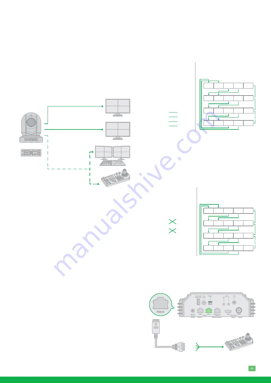
multiple cameras connection with SONY controller as 

below:

SONY Keyboard RS422 Connection

10.  How to make RS422 connection and RS422 Daisy Chain 

multiple cameras connection with Non-Sony controller 

as below: 

VISCA (Non-Sony) Keyboard RS422 Connection

11.  Use extension cables RJ45 to RS422 Phoenix connect-

er adaptor included to make RS422 connection for your 

control device.

Use RS422(VISCA) / RS485 (PELCO P/D)

You can use RS422/485 port connect to optional controllers, 

such as joystick control keyboard, control PC station, to op-

erate the camera.

To perform pan/tilt and zoom operations using the joystick 

of the control keyboard, and to perform the Preset operation 

using the control buttons. 

An application software that supports this unit is needed if 

you use PC station.

RS422 (VISCA) connection

1.  Set RS422 control method on Bottom Dip Switch.

2.  Set Baud Rate on Bottom Dip Switch to the same as Baud 

Rate setting on the keyboard you are using. 

3.  Set specific camera address that you want to control the 

camera for on Bottom Dip Switch.

4.  If you want to have the camera address to be automati-

cally assigned by VISCA controller, set camera Dip Switch 

address to 0. 

5.  Reboot the camera by turning it Off/On after the Bottom 

Dip Switch has been set up correctly. 

6.  Use the RJ45 to RS422 control cable. The controller must 

be VISCA compatible.

7.  Camera supports Daisy Chain connection up to 7 cam-

eras. 

8.  The connection of SONY keyboard is different than other 

VISCA (Non-Sony) keyboard.

HDMI Video Signal

SDI Video Signal

Remote Control Signal

(RS422 (VISCA)

or RS485 (Pelco P/D))

IR Remote Controller

Camera

5. GND

4. T +

3. T –

2. R +

1. R –

Keyboard

1.  --- 

2.  ---

3.  ---

4.  ---

5. GND

6. RXD IN –

7. RXD IN +

8. TXD IN –

9. TXD IN +

RS422 (VISCA) Daisy Chain

Multiple Cameras Connection

(SONY Keyboard)

RX +

RX –T

X +

TX –

GND

RX +

RX –T

X +

TX –

GND

RX +

RX –T

X +

TX –

GND

RX +

RX –

TX +

TX –

GND

KEYBOARD

CAM 1

CAM 2

CAM 7

SONY Keyboard

Connection

Camera

5. GND

4. TXD IN +

3. TXD IN –

2. RXD IN +

1. RXD IN –

Keyboard

1. GND

2. RXD IN –

3. RXD IN +

4. TXD IN –

5. TXD IN +

RS422 (VISCA) Daisy Chain

Multiple Cameras Connection

(VISCA Keyboard)

RX +

RX –T

X +

TX –

GND

RX +

RX –T

X +

TX –

GND

RX +

RX –T

X +

TX –

GND

RX +

RX –T

X +

TX –

GND

KEYBOARD

CAM 1

CAM 2

CAM 7

VISCA Keyboard

Connection

Multicore

Control

Cable

PTZ Keyboard

RS422 Serial Port

connection on

controller side

VCC-CC45RS

Extension cable RS422

adaptor included

5. R –

4. R +

3. T –

2. T +

1. GND

Summary of Contents for EYES P200

Page 1: ...EYES P200 FULL NDI NO COMPROMISES USER MANUAL PART 1...

Page 2: ...A connection 11 PELCO P D Keyboard RS485 Connection 12 Operating Multiple Cameras 13 VISCA over IP Control 13 DIP SWITCH SETTINGS 14 Adjusting and Setting with Menus 15 EXPOSURE Menu 15 WHITE BALANCE...

Page 3: ...nd other BirdDog s trademarks and logos are the property of BirdDog Australia Other trademarks company names and product names contained in this manual are the property of their respective owners Trad...

Page 4: ...a clean cloth with a bit of ethanol and wipe it gently If the camera will not be used for an extended period of time put on the lens cap to protect the sensor from dirt Do not aim the camera lens at t...

Page 5: ...tion Control supports RS 232 control RS 422 485 control VIS CA over IP NDI Control IR Remote Controller Presets store camera directions and image parameters Up to 6 presets on remote controller or 12...

Page 6: ...For original wall ceiling mount bracket 16 Tripod mounting holes 17 Bottom DIP Switch 1 12V DC Power Port Connect the supplied DC power adaptor and cord 2 USB 2 0 Port For firmware upgrade only 3 RS23...

Page 7: ...7 Auto Manual Focus 8 Back Light 9 Video Format Switching You can change the video format by keep pressing the button When video format is changed the camera would restart and the screen turns black...

Page 8: ...ut with HDMI video output 1 Connect SDI cable in between the camera your SDI De vice display 2 You now have SDI video output Power Use only the DC power adaptor JEITA type4 supplied with the unit Do n...

Page 9: ...the ways of controlling and typical system examples with the required components and usage of each system 1 Use the Infrared Remote Controller 2 Use RS 232 VISCA 3 Use RS 422 485 VISCA PELCO P D 4 ND...

Page 10: ...es included RJ45 to RS232 8 pin Mini Din adaptor to make RS232 connection for your control device RS 232 1 DTR 2 DSR 3 TXD 4 GND 5 RXD 6 GND 8 N C Camera or Mini DIN 8 pin serial 1 DTR 2 DSR 3 TXD 4 G...

Page 11: ...Switch 4 If you want to have the camera address to be automati cally assigned by VISCA controller set camera Dip Switch address to 0 5 Reboot the camera by turning it Off On after the Bottom Dip Switc...

Page 12: ...direct connect between the camera and the controller to make RS422 connection by following the pin definition below 13 How to make RS422 Daisy Chain multiple camera con nection with RS422 standard se...

Page 13: ...sport protocol UDP IP address 192 168 100 100 By default Port 52381 Or you can use CAT5 6 T 568B Standard Ethernet cable direct connect between the camera and the controller to make RS485 connection b...

Page 14: ...a is turned on the camera takes the last setting before it is turned on either set through the OSD or bottom DIP switch The Bottom DIP Switch Settings Bit 1 3 Camera Address setting for VISCA protocol...

Page 15: ...e displayed To change a set value use the button on the infra red remote controller NOTE In some product models only use button on the infrared remote controller to change the value To confirm the val...

Page 16: ...n is increased This is a function to put a limit on the shutter speed It prevents the camera shake when you shoot a moving subject in a dark place AE Response The slow AE Response function allows you...

Page 17: ...cture sharpness value ranges from 0 to 15 You can enjoy emphasized edge and high resolution images EFFECT Picture Effect It consists of the following func tions B W Monochrome Image Image effect from...

Page 18: ...u is used to select the pan tilt zoom mode DIGITAL ZOOM Set to DIGITAL ZOOM ON 12X digital zoom is activated You can set digital zoom to ON or OFF When set to OFF digital zoom does not operate and onl...

Page 19: ...t is activated You can cancel it by pressing the DATA SCREEN button Depending on the video client software you are using some video software may need to be restarted to obtain the new video format The...

Page 20: ...o activate the Fast Zoom Speed Mode press again to go back to normal Zoom Speed mode Operating Multiple Cameras with the Infrared Remote Controller MENU POWER CAMERA SELECT CAMERA SELECT 1 Set the DIP...

Page 21: ...to store the settings Recalling the stored settings Press any of the POSITION buttons 1 to 6 in which you have stored the settings CAMERA SELECT STD PRESET RESET REV Press a POSITION button While hol...

Page 22: ...22 Dimensions Unit mm 47 141 139 8 134 178 75 165 94 9 97 2 14 211...

Page 23: ...23...

Page 24: ...WELCOME TO THE FUTURE bird dog tv hello bi rd dog tv...

Reviews: