Belarus 80.1/80.2/82.1/82.2/82
Р — Operation and Service Manual
Section 7. Maintenance Procedures
91
c) keep the radiator clean, cleanse it at
regular intervals;
d) check the fan drive belt for proper
tension every 125 hours of diesel-
engine operation (during scheduled
maintenance service MS-1). Tension
of belt sections between the pulleys
of the crankshaft and the alternator
should be such as to sag 15-22 mm,
when a 40 N pressure is applied to
the belt. Tension is adjusted by relo-
cating the alternator body by turning;
e) when required, and at intervals of
not more than 2000 hour of diesel-
engine operation, clean the cooling
system from scale. To do this, fill it
up with a solution of 50-60 g soda
ash and 1 l water; start the diesel-
engine and let it run for 8…10 hours.
Then, stop the diesel-engine, drain
the solution from the system, and
flush it through with fresh water;
f) the water pump of the cooling sys-
tem houses bearings and end pack-
ing, which do not require servicing
throughout the tractor service life.
MAINTENANCE OF THE AIR CLEAN-
ER
Service the air cleaner every 1000 hours
of diesel-engine operation, as well as
when the air filter clogged warning lamp
alights
– indicating its extreme blocking
condition.
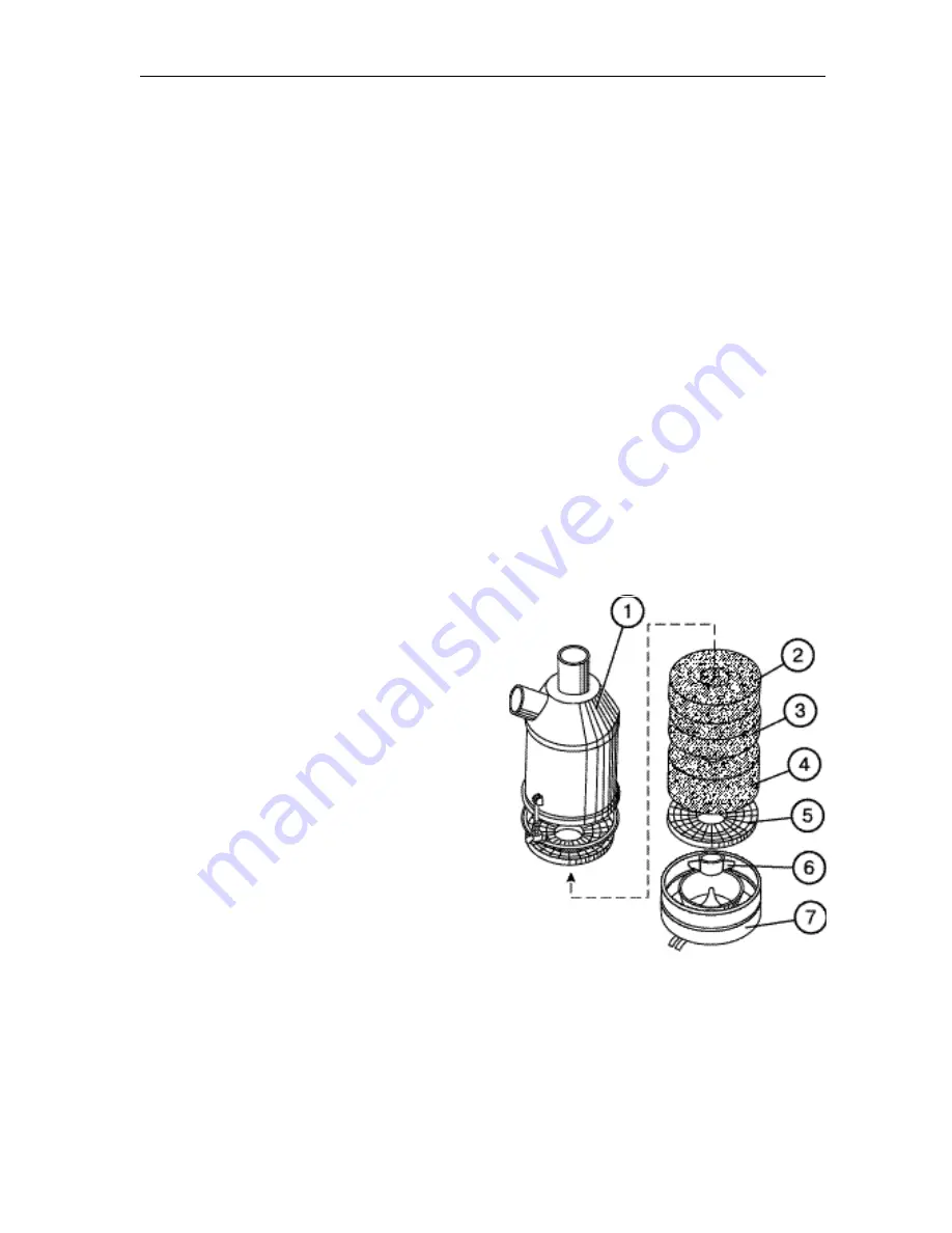
To service the air cleaner, proceed as
follows (see Fig. 41):
а) remove the air cleaner from the die-
sel-engine, dismantle it (separate the
pan and remove filter elements from
the housing);
b) clean and wash the pan (7), housing
(1) and central pipe in diesel fuel;
wash the filter elements. Let the die-
sel fuel run off, blow the details
through with compressed air, and
reassemble the air cleaner. Refit it
on the diesel-engine;
c) fill the pan (7) with oil up to the ring
shoulder and refit it back in place;
d) check all the connection and joints of
the air cleaner and air inlet pipeline;
to do this, with the monocyclon re-
moved and the diesel-engine run-
ning at intermediate r.p.m., shut off
the central tube of the air cleaner; as
this takes place, the diesel-engine
should quickly stall. Otherwise, iden-
tify and remove the leakages
through joints;
e) after washing, reassemble the filter
elements (2, 3 and 4) in the following
order: first, element (2) (black), with
the smallest diameter of thread (0.2
mm); then
— filter element (3), with
an intermediate diameter (0.24 mm),
and at last
— filter element (4), with
the largest diameter (0.4 mm) of
thread. Thereafter, install the cage
(5) and detent (6).
Fig. 41


