background image

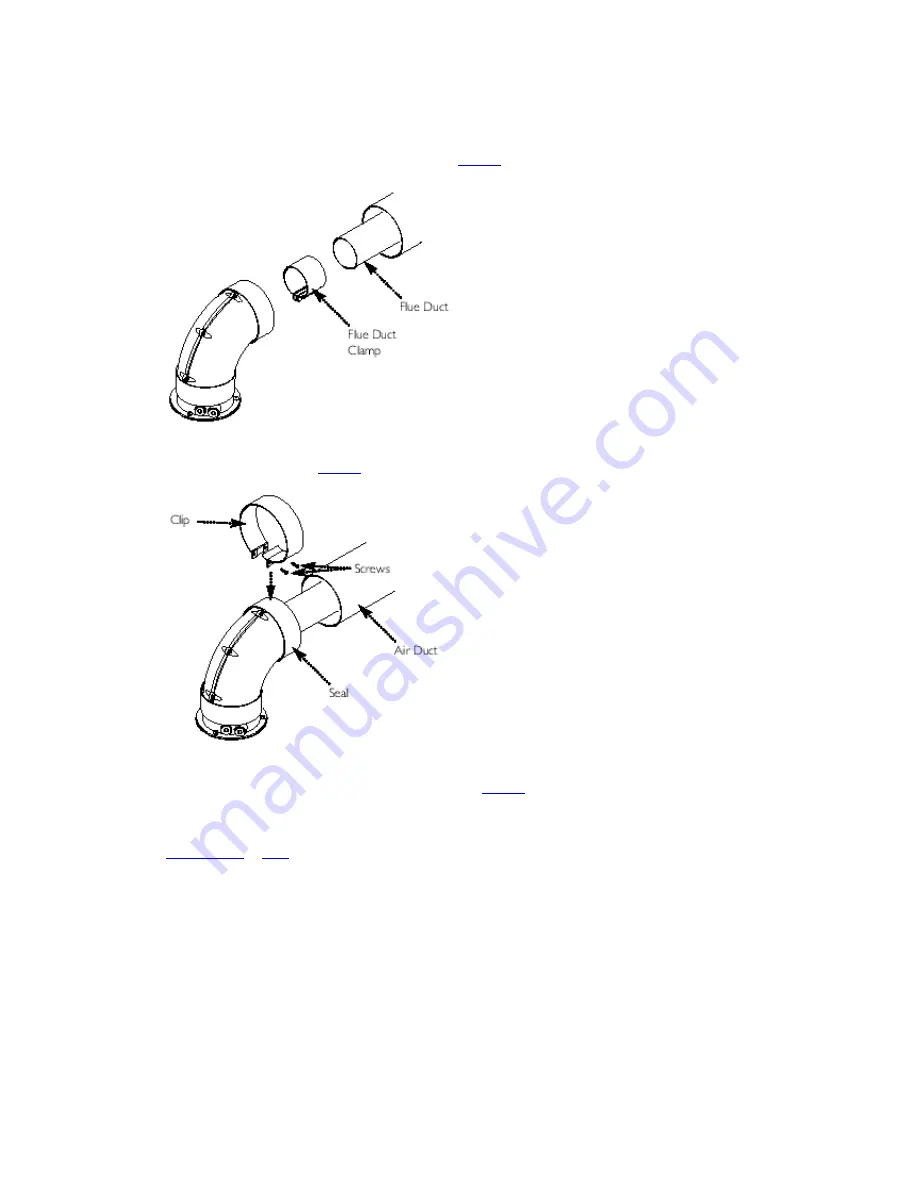
10. Refit the screws to the clip and tighten them to secure the elbow. Take the second rubber 
seal and position it on the flue elbow. 
11. Locate the flue duct clamp on the flue outlet elbow. Draw the flue duct out of the air duct, 
engage it in the clamp and tighten the screws (

Fig. 22

). 


Fig. 22


12. Draw the air duct out of the wall and align it with the elbow. Position the seal so that it 
equally covers the joint (

Fig. 23

). 


Fig. 23


13. Remove the screws from the second clip provided. Prise the clip apart and fit it over the 
seal. Refit the screws to the clip and tighten them (

Fig. 23

). 

14. Where possible position the clips so that the screws are not visible. 
15. Make good between the wall and air duct outside the building. 
16. Fit the circular flue trim outside if required, and if necessary fit a terminal guard (see 

Section 7.10

 & 

7.11

). 

8.7 Extensions & Additional Elbows 

1. The method of connecting any flue extensions or additional elbows is the same as that for 
connecting the standard flue and 90°elbow as described above. 
2. If, for example, when a flue extension is connected to a 90°elbow the flue duct will project 
from the air duct at the unconnected end by the same amount as the flue duct spigot does 
from the elbow . Further elbows or extensions can then be added to this. 
3. Similarly, a concentric flue can be connected to the boiler adaptor in the same manner as it 
does to the elbow to provide a vertical flue. 
4. The additional 90°elbow available is identical to the elbow supplied with the standard flue. 
45°elbows are of the same principle. 
5. Extensions can be cut according to the requirements of the installation. 

Summary of Contents for 35/80 IE

Page 1: ...n Servicing Instructions Baxi System 35 80 IE 60 100 IE Gas Fired Wall Mounted System Boiler Please keep these instructions safe Should you move house please hand them over to the next occupier Page 1 Natural Gas ...

Page 2: ...roducts that customers want to buy Everyone who works at Baxi has a commitment to quality because we know that satisfied customers mean continued success We hope you get a satisfactory service from Baxi If not please let us know The boiler meets the requirements of Statutory Instrument The Boiler Efficiency Regulations 1993 No 3083 and is deemed to meet the requirements of Directive 92 42 EEC on t...

Page 3: ...Dimensions and Fixings 9 6 0 System Details 10 7 0 Site Requirements 12 8 0 Installation 17 9 0 Commissioning the Boiler 26 10 0 Completion 28 11 0 Servicing the Boiler 29 12 0 Changing Components 31 13 0 Illustrated Wiring Diagram 39 14 0 Fault Finding 40 15 0 Short Parts List 43 Page 3 1 0 Introduction ...

Page 4: ... for use only on fully pumped sealed systems 5 The boiler data badge gives details of the model and serial number and is situated on the control box It is visible when the case front panel is removed Fig 1 Fig 1 NOTE This appliance must be installed in accordance with the manufacturer s instructions and the regulations in force Read the instructions fully before installing or using the appliance 6...

Page 5: ...c Gas Installations the current Building Regulations and reference should be made to the current ETCI Rules for Electrical Installation 1 3 Optional Extras Various flue extensions bends vertical flue kits control accessories etc are available as optional extras These are detailed in a separate publication Page 4 2 0 General Layout ...

Page 6: ...urner 15 Primary Heat Exchanger 16 Fan Assembly 17 On Off Reset Selector Switch 18 Central Heating Temperature Control 19 Flame Failure 20 Safety Thermostat 21 Fault on Fan or Flue 22 Fault on Pump or Low System Pressure 23 Temperature Indication Only 24 Fault on Central Heating Sensor 25 Power On 26 Hot Water Mode 27 Central Heating Mode 28 Burner On When neons 19 to 24 are constantly illuminated...

Page 7: ...oiler Primary Circuit 3 1 Operating Mode Fig 2 Fig 2 Key 1 Heat Exchanger 2 Burner 3 Ignition Electrode 4 Flame Sensing Electrode 5 Gas Valve 6 Pump 7 Automatic Air Vent 8 Pressure Relief Valve 9 Boiler Drain Point 10 Gas Inlet ...

Page 8: ...e pump continues to run for a period of 3 minutes Pump Overrun IMPORTANT When the selector switch is in the 0 Off position the electrical supply to the boiler is isolated The boiler will not operate 3 2 Frost Protection Mode 1 The frost protection mode is integral to the appliance and functions only with the selector switch see Section 2 1 in the domestic hot water and central heating position If ...

Page 9: ...essure Natural Gas G20 mbar 20 in wg 8 Burner Injector Natural Gas G20 12 x 1 28mm Diameter Electrical Supply 230V 50Hz Appliance must be connected to an earthed supply Power Consumption 170W External Fuse Rating 3A Maximum Internal Fuse Rating Fuse 2A Fast Blow to BS 4265 Electrical Protection IPX5D NOx Class 3 Flue Terminal Diameter 100mm Dimensions Projection 95mm Connections copper tails Gas S...

Page 10: ...0 mm Min For Servicing Front 5 mm Min In Operation Weights kg Packaged Boiler Carton 45 Packaged Flue Kit 3 Installation Lift Weight 37 Central Heating Primary Circuit Pressures bar Safety Discharge 3 Max Operating 2 5 Min Operating 0 2 Recommend Operating 1 2 Pump Grundfos UP 15 60 Available Head See graph below Expansion Vessel Integral with appliance bar Min Pre charge Pressure 0 5 litre Max Ca...

Page 11: ...mbar 28 8 0 5 7 7 0 5 in wg 11 5 0 2 3 1 0 2 Inlet Pressures Propane Butane mbar 37 28 30 in wg 14 8 11 2 SEDBUK Declaration For System Boiler 35 80 IE The seasonal efficiency SEDBUK is 78 6 This value is used in the UK Government s Standard Assessment Procedure SAP for energy rating of dwellings The test data from which it has been calculated have been certified by 0051 Page 7 Appliance Type C12 ...

Page 12: ...essure Natural Gas G20 mbar 20 in wg 8 Burner Injector Natural Gas G20 15 x 1 28mm Diameter Electrical Supply 230V 50Hz Appliance must be connected to an earthed supply Power Consumption 190W External Fuse Rating 3A Maximum Internal Fuse Rating Fuse 2A Fast Blow to BS 4265 Electrical Protection IPX5D NOx Class 3 Flue Terminal Diameter 100mm Dimensions Projection 95mm Connections copper tails Gas S...

Page 13: ...5 mm Min In Operation Weights kg Packaged Boiler Carton 47 Packaged Flue Kit 3 Installation Lift Weight 39 Central Heating Primary Circuit Pressures bar Safety Discharge 3 Max Operating 2 5 Min Operating 0 2 Recommend Operating 1 2 Pump Grundfos UP 15 60 Available Head See graph below Expansion Vessel For Central Heating only Integral with appliance bar Min Pre charge Pressure 0 5 litre Max Capaci...

Page 14: ...0 0 2 Inlet Pressures mbar 37 in wg 14 8 SEDBUK Declaration For System Boiler 60 100 IE The seasonal efficiency SEDBUK is 78 2 This value is used in the UK Government s Standard Assessment Procedure SAP for energy rating of dwellings The test data from which it has been calculated have been certified by 0051 Page 8 5 0 Dimensions and Fixings Dimensions A 780mm B 345mm C 450mm D 107mm Ø Min E 200mm...

Page 15: ...F 190mm G 143mm ...

Page 16: ...ent of Water Circulating Systems All recirculatory water systems will be subject to corrosion unless an appropriate water treatment is applied This means that the efficiency of the system will deteriorate as corrosion sludge accumulates within the system risking damage to pump and valves boiler noise and circulation problems ...

Page 17: ... accordance with the manufacturer s instructions Test kits are available from inhibitor stockists For information or advice regarding any of the above contact Heatmerchants Technical Enquiries on 090 6442303 6 2 Bypass 1 The boiler is fitted with an automatic integral bypass 6 3 System Control 1 The boiler is designed for use in a heating system that incorporates external controls i e a minimum of...

Page 18: ...loop can be assembled 6 5 Expansion Vessel 1 The appliance expansion vessel is pre charged to 0 5 bar The vessel is suitable for correct operation for system capacities up to 125 litres For greater system capacities an additional expansion vessel must be fitted refer to the current edition of I S 813 6 6 Pressure Relief Valve Fig 4 Fig 4 ...

Page 19: ... Site Requirements 7 1 Information The installation must be carried out by a Competent Person and installed in accordance with the current edition of I S 813 Domestic Gas Installations the current Building Regulations and reference should be made to the current ETCI Rules for Electrical Installation 7 2 Codes of Practice Standard Scope I S 813 Domestic Gas Installations BS 5546 Installation of hot...

Page 20: ...Fig 5 ...

Page 21: ...tected by a suitable enclosure i e garage or outhouse The boiler may be fitted inside a cupboard see Section 7 5 2 If the boiler is sited in an unheated enclosure then it is recommended to leave the On Off Reset Selector Switch in the domestic hot water and central heating position to give frost protection 3 If the boiler is fitted in a room containing a bath or shower reference must be made to th...

Page 22: ...ler diameter than the boiler gas connection 3 4 7 7 Electrical Supply 1 External wiring must be correctly earthed polarised and in accordance with current edition of the ETCI Rules 2 The mains supply must be 230V 50Hz and fused at 3A maximum NOTE The method of connection to the electricity supply must facilitate complete electrical isolation of the appliance Connection may be via a fused double po...

Page 23: ...ns given in the current edition of I S 813 2 The terminal shall be located in such a position that the wind can freely blow across it at all times that the products of combustion will not be blown into nearby air entry grills or roof spaces or cause discomfort to passers by 3 A suitable guard shall protect terminals located less than 2 m above any level to which people have normal access Fig 9 Ter...

Page 24: ...ere the exhaust is directed upwards otherwise 1000 Page 14 7 9 Flue Dimensions The standard horizontal flue kit allows for flue lengths between 100mm and 1m from elbow to terminal Fig 10 Fig 10 The maximum permissible equivalent flue length is System 35 80 IE 5 metres System 60 100 IE 4 metres 7 10 Flue Terminal Trim 1 Once the flue is secure the trim can be fitted if required 2 Remove the protect...

Page 25: ...Terminal Guard Fig 13 1 When codes of practice dictate the use of terminal guards they can be obtained from most Plumbers and Builders Merchants 2 There must be a clearance of at least 50mm between any part of the terminal and the guard 3 When ordering a terminal guard quote the appliance name and model number ...

Page 26: ...4 The flue terminal guard should be positioned centrally over the terminal and fixed as illustrated Page 15 7 12 Flue Options ...

Page 27: ...s The elbow supplied with the standard horizontal flue is not included in any equivalent length calculations 5 The illustrations opposite show examples of maximum equivalent lengths 6 Full details of part numbers and descriptions of all optional flue components and kits can be found in the Baxi Flue Guide 7 Instructions for guidance and fitting are included in each kit where appropriate Page 16 8 ...

Page 28: ...s 3 Mark the position of the centre of the flue hole rear exit For side flue exit mark as shown 4 Note the shaded area on the template Pipework may be routed upwards behind the boiler providing it does not conflict with the shaded area 5 If required mark the position of the gas and water pipes Remove the template 6 Cut the hole for the flue minimum diameter 107mm ...

Page 29: ...central heating flow or return pipe Fig 15 Fig 15 2 Flush thoroughly see System Details Section 6 1 8 3 Preparing The Boiler 1 Remove all packaging 2 Stand the boiler on its base by using the rear lower edge as a pivot NOTE A small amount of water may drain from the boiler in the upright position Baxi declare that no substances harmful to health are contained in the appliance or used during applia...

Page 30: ...ling washers between the valves and pipes on the wall plate and the boiler connections The rubber washers must be used on the gas connection 4 Tighten all the connections 8 5 Fitting the Pressure Relief Discharge Pipe Fig 17 ...

Page 31: ...d tighten the nut 5 Complete the discharge pipework and route it to the outside discharge point IMPORTANT Make all soldered joints before connecting to the pressure relief valve Page 18 8 6 Fitting The Flue HORIZONTAL FLUE 1 The standard flue is suitable for lengths 100mm minimum to 1m maximum measured from the edge of the flue elbow outlet Rear Flue maximum wall thickness 900mm Side Flue maximum ...

Page 32: ...s shown Fig 19 Measure the length of waste material and transfer the dimension to the flue duct Fig 19 Fig 19 IMPORTANT Check all measurements before cutting 5 Remove the waste from both ducts Ensure that the cut ends are square and free from burrs ...

Page 33: ...1 5m the restrictor MUST be removed from the adaptor Fig 20 Fig 20 8 Take one of the rubber seals and position it on the boiler flue adaptor Engage the flue elbow on the adaptor and pull the sleeve up so that it equally covers the joint Fig 20 9 Remove the screws from one of the clips provided Prise the clip apart and fit it over the seal Fig 21 Set the elbow to the required angle Fig 21 ...

Page 34: ...uilding 16 Fit the circular flue trim outside if required and if necessary fit a terminal guard see Section 7 10 7 11 8 7 Extensions Additional Elbows 1 The method of connecting any flue extensions or additional elbows is the same as that for connecting the standard flue and 90 elbow as described above 2 If for example when a flue extension is connected to a 90 elbow the flue duct will project fro...

Page 35: ... connect the mains input cable proceed as follows 1 Slacken the facia securing screws and lift the outercase panel so that its securing tabs are clear of the facia Remove the panel 2 Remove the screws securing the facia panel and hinge it down Fig 24 ...

Page 36: ...trol through the second cable clamp on the boiler chassis Refer to the instructions supplied with the control 7 To connect external control s remove the link between terminals 1 2 The switched output from the external control must be connected to terminal 2 Fig 27 8 Any domestic hot water control should be connected to the DHW relay PCB Fig 24 in most installations See Section 8 9 for details of s...

Page 37: ...n In Scheme 1 the boiler does not differentiate between central heating and domestic hot water demands With Schemes 2 3 4 the boiler utilises the benefit of the integral domestic hot water thermostat referred to above which overrides any temperature requirements of the central heating control s 6 It is recommended that the central heating temperature control is always set at maximum Scheme 1 IMPOR...

Page 38: ...be relied upon to limit the temperature of DHW 11 The selector switch must be in the central heating and domestic hot water position at all times for the boiler to operate Page 22 Scheme 2 Scheme 2 b blue w white o orange br brown gr grey g y green yellow 12 Scheme 2 incorporates two 2 port zone valves and is based on an S plan system The boiler will provide hot water to the central heating system...

Page 39: ...re is a demand for domestic hot water and the cylinder thermostat is not satisfied the zone valve will be energised to open port A 19 The zone valve is installed so that port A is connected to the domestic hot water circuit and port B to central heating This is the reverse of a conventional W plan It ensures that the valve is energised only when there is a hot water demand not for long periods i e...

Page 40: ...dard Y plan to Scheme 4 proceed as follows i Change the orientation of the zone valve so that port A serves domestic hot water and port B the central heating ii Remove the wire between 7 on the terminal strip and terminal 2 of the cylinder thermostat iii Disconnect the orange zone valve wire from 8 on the terminal strip and connect to 9 iv Disconnect the grey zone valve wire from 7 on the terminal...

Page 41: ...ia securing screws sufficiently to release the outercase panel securing tabs Lift and remove the panel 2 Remove the screws securing the facia panel and hinge it down 3 Slacken the cable clamp on the R H side of the boiler chassis Insert the cable from the cylinder thermostat through the cable clamp 4 Undo the screws securing the DHW relay PCB cover Remove the cover Slacken the screws in the termin...

Page 42: ...llow the control box to drop down Tighten the cable clamp on the boiler chassis 8 11 Preliminary Electrical Checks 1 Prior to commissioning the boiler preliminary electrical system checks should be carried out 2 These should be performed using a suitable meter and include checks for Ground Continuity Resistance to Ground Short Circuit and Polarity Page 25 ...

Page 43: ...S 7593 and the flushing agent manufacturers instructions further guidance can be obtained from BS 5449 Section 5 4 Pressurise the system to at least 0 2 bar then close and disconnect the filling loop 5 Turn the gas supply on and purge according to I S 813 6 Test for gas soundness 7 If at any time during commissioning it is required to terminate a particular cycle e g the pump overrun period turn t...

Page 44: ...e Burner Pressure 1 Turn on the gas and electrical supplies to the boiler and ensure that all external controls are calling for heat 2 Set the temperature control to maximum and the selector switch to the Off position Fig 36 ...

Page 45: ...l Lift the panel slightly to disengage it from the studs on top of the case 5 IMPORTANT Turn the selector switch fully anticlockwise against the spring pressure to position R and hold for at least 3 seconds to reset the boiler 6 Turn the selector switch to the Cental Heating and Domestic Hot Water position The power On neon will illuminate Fig 36 ...

Page 46: ...ressure adjustment nuts on the valve 11 The smaller nut 5mm adjusts minimum pressure and the larger nut 8mm maximum pressure 12 Using a suitable spanner adjust the relevant nut until the correct pressure is achieved 13 Once the pressure has been set turn the boiler off and disconnect the pressure gauge 14 Tighten the pressure test screw and refit the modulator to the valve Reassemble in reverse or...

Page 47: ... is serviced annually Servicing must be performed by a competent person 2 Ensure that the boiler is cool 3 Ensure that both the gas and electrical supplies to the boiler are isolated 4 Slacken the screws securing the facia panel Lift the outercase panel so that its securing tabs are clear of the facia Remove the panel Fig 38 Fig 38 5 Remove the facia securing screws and hinge the panel down 6 Remo...

Page 48: ... upwards as far as possible Fig 40 9 Remove the four screws securing the combustion box door and remove the door Fig 39 Page 29 10 Remove the spring clips retaining the air box side baffle plates Disengage the tabs on the baffles from the slots in the fan hood Fig 41 ...

Page 49: ...l only Draw the burner out of the combustion box pulling the electrode grommets from the slots in the combustion box lower panel Fig 43 13 Disconnect the electrode leads and grommets from the electrodes Completely remove the burner Fig 43 14 Brush any deposits from the injectors Do not use a pin or wire to clean them 15 Brush the burner blades and venturis and clean the combustion box ...

Page 50: ...e boiler before recommissioning Page 30 12 0 Changing Components IMPORTANT When changing components ensure that both the gas and electrical supplies to the boiler are isolated before any work is started When the new component has been fitted turn the selector switch fully anticlockwise against the spring pressure to position R and hold for at least 3 seconds to reset the boiler before recommission...

Page 51: ......

Page 52: ...et sealing collar Ease the collar upwards as far as possible 3 Remove the four screws securing the combustion box door and remove the door 4 Remove the spring clips retaining the air box side baffle plates Disengage the tabs on the baffles from the slots in the fan hood 5 Undo the screws securing the fan hood to the appliance back panel and draw the fan and hood assembly forwards 6 Remove the scre...

Page 53: ...n and hood assembly forwards 6 Drain the primary circuit Prise the two pipe connecting clips off the joints in the flow and return pipes 7 Lift the heat exchanger to disconnect the flow and return pipe joints Withdraw it from the appliance taking care not to damage the rear insulation piece 8 Fit the new heat exchanger 9 Reassemble in reverse order of dismantling and repressurise the system 12 4 B...

Page 54: ... 4 Undo the screws securing the electrodes to the burner Examine the condition of the electrodes replacing if necessary Fit the electrodes to the new burner 5 Engage the burner location brackets over the studs on the injector manifold and reassemble in reverse order Page 32 12 5 Injectors Fig 49 ...

Page 55: ......

Page 56: ...s from the slots in the combustion box lower panel 3 Disconnect the lead and grommet from the electrode being replaced Undo the securing screw and withdraw the electrode to the burner 4 Reassemble in reverse order 12 7 Insulation Fig 50 1 Remove the four screws securing the combustion box door and remove the door 2 Slide the side insulation pieces carefully out of their carriers 3 To replace the r...

Page 57: ......

Page 58: ...and outlet manifold to the new valve ensuring that the O ring seals are in place 10 Reassemble in reverse order and check the burner pressure as described in Section 9 2 12 9 Central Heating Temperature Sensor Fig 52 1 Ease the retaining tab on the sensor away and disconnect the electrical plug 2 Unscrew the sensor from it s pocket and reassemble in reverse order The plug will only fit one way 12 ...

Page 59: ......

Page 60: ... automatic air vent from the pump body Undo the two screws securing the body to the pipe and manifold and draw the pump forwards 2 Undo the screw on the pump wiring cover and remove the cover Using a suitable flat bladed screw driver press the cable securing levers downwards to release each wire after noting their position 3 Connect the wiring to the new pump Examine the O ring seals on the return...

Page 61: ...move the DHW relay PCB cover and ease the wiring aside Undo the screws securing the gauge retaining bracket 3 Remove the bracket and gauge assembly Depress the barbs on the side of the gauge and remove the retaining bracket 4 Reassemble in reverse order 12 16 Expansion Vessel Fig 59 ...

Page 62: ...r off the wall plate and lay it on either side on a clean flat surface 4 Undo the nut on the vessel outlet spigot and remove the locknut and spring washer securing the spigot to the boiler chassis 5 Undo the screws and remove the appliance upper cross member Slide the expansion vessel out of the retaining clips 6 Reassemble in reverse order Fully recommission the appliance and system 12 17 Gas Val...

Page 63: ...ing the control box cover and release the cover retaining barbs from their slots Disengage the rear tabs of the cover from the control box hinge pin 4 Remove the plug lead from the cable clip and disconnect the multi pin plug from the PCB 5 Reassemble in reverse order Page 36 12 18 DHW Relay PCB Fig 62 1 Undo the screws securing the DHW relay PCB cover Remove the cover ...

Page 64: ...and remove the PCB Transfer the control knob drive pin to the new PCB and turn it fully anticlockwise 5 Reassemble in reverse order ensuring that the temperature controller is reset to the previous position 6 Ensure that the DHW potentiometer is fully anticlockwise once the new PCB is fitted 7 IMPORTANT Turn the selector switch fully anticlockwise against the spring pressure to position R and hold...

Page 65: ... the bypass connecting clips and disconnect the heating flow tap Undo the screws securing the valve to the boiler bottom panel Remove the valve 5 Remove the screws securing the cover from the valve body Examine the condition of the diaphragm spring and pushrod replacing as necessary 6 If required the complete valve assembly can be replaced 7 Examine the sealing washers and O ring on the pipes and ...

Page 66: ...elief Valve Fig 65 Fig 65 1 Drain the primary circuit 2 Disconnect the discharge pipe from the valve Using a suitable hexagon key undo the grub screw sufficiently to release the valve 3 Note the orientation of the valve rotate it and withdraw it from the manifold 4 Fit the new valve and O ring seal and set to the previously noted orientation Reassemble in reverse order Page 38 13 0 Illustrated Wir...

Page 67: ...br brown bk black b blue r red g green g y green yellow w white Page 39 14 0 Fault Finding ...

Page 68: ...with a suitable meter NOTE These checks must be repeated after any servicing or fault finding 3 Ensure all external controls are calling for heat and check all external and internal fuses Before any servicing or replacement of parts ensure the gas and electrical supplies are isolated Refer to Section 13 0 Illustrated Wiring Diagram for position of numbered terminals Central Heating Follow operatio...

Page 69: ...Page 40 Fault Finding Solutions Sections A to E ...

Page 70: ...Page 41 ...

Page 71: ......

Page 72: ...66 398 Burner 35 80 IE 248029 E66 399 Burner 60 100 IE 248030 44 Injector 248210 59 E66 408 Electrode Lead 248037 63 E66 411 Spark or Sensing Electrode 247384 72 E66 539 Pump 248042 102 Hydraulic Outlet Assy 248490 131 342 571 Temperature Sensor 247394 135 E66 439 Safety Thermostat 248079 140 Gas Valve 5107339 154 PCB 5112380 156 DHW Relay PCB 248620 169 E66 453 Pressure Gauge 248090 528 Return He...

Page 73: ......

Page 74: ......

Page 75: ...Page 43 Comp No 5113935 Iss 01 10 04 After Sales Service 090 6442303 Technical Enquiries 090 6442303 HEATMERCHANTS Moydrum Road Athlone Co Westmeath www heatmerchants ie 923 858 1 Page 44 ...

Reviews: