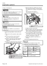
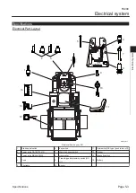
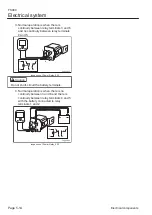

Brake pedal switch
The brake pedal switch is one of the safety
switches that constitute the interlock system.
It is located on the brake fulcrum.
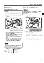
Power relay CA1-DC12V-N
This relay is related to the brake pedal
switch, traveling pedal proximity switch, and
seat switch, and controls engine activation
and retention.
This is located inside the front cover.
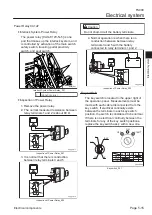
Power relay MR5A602A1K
This relay is related to the parking brake
switch, traveling pedal proximity switch, and
seat switch, and controls engine activation
and retention.
This is located inside the front cover.
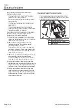
Fuse
This is the main fuse for the entire electrical
circuit.
This is located inside the front cover beneath
the key switch.
Pilot lamp
This is related to the sensor inside the
bucket, and blinks in red if the collections
reach the bucket capacity.
It is located in the upper left area of the
operation panel.
Key switch
This is used to start, run, or stop the engine.
It is located in the lower right area of the
operation panel.
Warning buzzer switch
This is related to the sensor inside the
bucket. While the warning buzzer switch is
turned ON during work, an intermittent
buzzer sounds and the warning lamp lights
up when the collections reach the bucket
capacity.
It is located in the upper right area of the
operation panel.
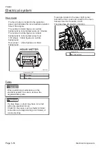
Hour meter
This indicates the total operation time of the
engine. The periodical check and
maintenance schedule is based on the
number of hours indicated on this meter.
It is located in the lower right area of the
operation panel.
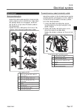
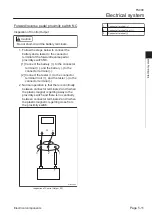
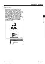
Traveling pedal proximity switch [NC (+)]
The traveling pedal proximity switch is one of
the safety switches that constitute the
interlock system.
1.
2.
3.
4.
5.
6.
7.
8.
9.
A plastic magnet for detection is attached to
the traveling pedal arm section. This
traveling pedal proximity switch detects that
the magnet is not close by.
This is located near the traveling pedal.
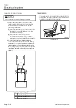
Buzzer
This is related to the sensor. When the
warning buzzer switch is turned ON, an
intermittent buzzer sounds when the
collections reach the bucket capacity.
This is located inside the front cover.
Seat switch [NC type (push to turn off)]
The seat switch [NC type (push to turn off)]
is one of the safety switches that constitute
the interlock system. It is located in the
center of the seat.
Sensor
This is related to the warning buzzer and
pilot lamp, and emits an electric signal if the
collections reach the bucket capacity.
This is located on the left side surface inside
the bucket.
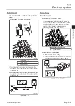
Magnetic switch
This switch supplies power to the starter
motor when the key switch is in the start
position.
It is located below the fuel tank inside the
main unit left cover.
Battery
The battery supplies power to the starter
motor as well as to all electrical parts at
engine startup.
This is located inside the cover on the left
side of the main unit.
Special Tool
Special tools list
No use of special tools is required.
10.
11.
12.
13.
14.
FS900
Electrical system
Page 5-4
Special Tool
Summary of Contents for FS900
Page 1: ...Riding Sweeper Service Manual Serial No FS900 10001 Ver 1 0...
Page 4: ...FS900 Contents...
Page 10: ...FS900 Safety Page 1 6 Safety Signs and Instruction Signs...
Page 11: ...Waste Disposal Page 2 2 About the Waste disposal Page 2 2 Disposal FS900 Disposal Page 2 1...
Page 28: ...FS900 Maintenance standards and maintenance Page 3 16 Greasing...
Page 74: ...FS900 Hydraulic system Page 4 46 Inspection and repair of each section...
Page 98: ...FS900 Electrical system Page 5 24 General inspection and repair...
Page 118: ...FS900 Main body Page 6 20 Inspection and repair of each section...