2. General
Which screen type ?
There are two major categories of screens used for projection equipment. Those used for front projected images and those for rear
projection applications.
Screens are rated by how much light they re
fl
ect (or transmit in the case of rear projection systems) given a determined amount
of light projected toward them. The ‘GAIN’ of a screen is the term used. Front and rear screens are both rated in terms of gain.
The gain of screens range from a white matte screen with a gain of 1 (x 1) to a brushed aluminized screen with a gain of 10 (x 10)
or more. The choice between higher and lower gain screens is largely a matter of personal preference and another consideration
called the viewing angle. In considering the type of screen to choose, determine where the viewers will be located and go for the
highest gain screen possible. A high gain screen will provide a brighter picture but reduce the viewing angle. For more information
about screens, contact your local screen supplier.
What image size? How big should the image be?
The projector is designed for projecting an image size : minimum 2 meter (6.6 ft.) to maximum 10 meter (32.8 ft.) (depending on
the ambient light conditions), with an aspect ratio of 4 to 3 .
2.2
Unpacking the projector
What has to be done ?
At delivery the projector is packed in a cardboard box upon a wooden pallet and secured with banding and fastening clips. Futher-
more, to provide protection during transport, the projector is surrounded with foam. Once the projector has arrived at the installation
site, it has to be removed from the cardboard box and wooden pallet in a safe manner without damaging the projector.
Necessary tools
Side cutter
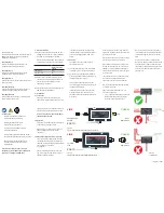
How to unpack the projector
1. Remove the banding around the carton box, by releasing the fastening clips.
2. Cut open the box but do not insert the cutter too deep, otherwise the projector could be damaged.
Image 2-1
3. Take out the cardboard box with the accessories such as manuals, remote control and power cord.
4. Take the projector out of the cardboard box and place it on a stable table.
12
R59770021 CLM R10+ 15/03/2010
Summary of Contents for R9050100
Page 1: ...CLM R10 Users manual R9050100 R90501001 R59770021 10 15 03 2010...
Page 14: ...1 Safety 10 R59770021 CLM R10 15 03 2010...
Page 22: ...2 General 18 R59770021 CLM R10 15 03 2010...
Page 35: ...3 Physical installation Skew Image 3 28 Skew adjustment R59770021 CLM R10 15 03 2010 31...
Page 36: ...3 Physical installation 32 R59770021 CLM R10 15 03 2010...
Page 48: ...5 Connections 44 R59770021 CLM R10 15 03 2010...
Page 64: ...7 Start up of the Adjustment mode 60 R59770021 CLM R10 15 03 2010...
Page 74: ...8 Input menu 70 R59770021 CLM R10 15 03 2010...
Page 116: ...10 Layout menu 112 R59770021 CLM R10 15 03 2010...
Page 158: ...13 Projector control 154 R59770021 CLM R10 15 03 2010...
Page 172: ...14 Service menu 168 R59770021 CLM R10 15 03 2010...
Page 186: ...16 Servicing 182 R59770021 CLM R10 15 03 2010...
Page 196: ...17 Projector covers removal and installation 192 R59770021 CLM R10 15 03 2010...
Page 204: ...C DMX Chart 200 R59770021 CLM R10 15 03 2010...
Page 210: ...D Specifications 206 R59770021 CLM R10 15 03 2010...
Page 216: ...E Troubleshooting 212 R59770021 CLM R10 15 03 2010...
Page 222: ...F Mounting optional Carry handle 218 R59770021 CLM R10 15 03 2010...
Page 224: ...G Order info 220 R59770021 CLM R10 15 03 2010...