background image

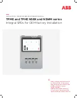
•  Model numbers covered by this manual 

are TPME and TPHE, UL Type 2 model 
types ending with part number suffixes 
of NSBX and NSWM. (Example: 
TPHE277Y20NSBX)

•  Model types are also available with a  

UL Type 1 rating. These models will be 
labeled with the part number suffix of T1.

INSTALL ATION, OPER ATION AND MAINTENANCE MANUAL 

TPME and TPHE NSBX and NSWM series 

Integral SPDs for OEM factory installation

Summary of Contents for TPME Series

Page 1: ...umber suffixes of NSBX and NSWM Example TPHE277Y20NSBX Model types are also available with a UL Type 1 rating These models will be labeled with the part number suffix of T1 INSTALLATION OPER ATION AND MAINTENANCE MANUAL TPME and TPHE NSBX and NSWM series Integral SPDs for OEM factory installation ...

Page 2: ...igueur dans le pays lieu où l appareil est utilisé WARNING Do not HIPOT the SPD unit or the electrical system to which the SPD unit is connected without disconnecting the SPD unit s conductors including phases neutral and ground Ne procédez PAS à des ESSAIS DE RIGIDITÉ DIÉLECTRIQUE sur le SPD ou le système électrique auquel il est connecté sans déconnecter les conducteurs des SPD y compris les pha...

Page 3: ... diagram EXAMPLE OF AN NEC COMPLIANT GROUNDING ARRANGEMENT FOR A SEPERATELY DERIVED SYSTEM for an example of an installation that complies with these NEC recommendations Verify that there have not been multiple instances of neutral to ground bonds on the electrical system These bonds while either intentional or accidental result in ground currents that can create differential voltage potentials be...

Page 4: ...se 3 wire ground TPME TPHE120Y TPME TPHE220Y TPME TPHE240Y TPME TPHE277Y TPME TPHE347Y 120 208 V 220 380 V 240 415 V 277 480 V 347 600 V 150 V L N L G 320 V L N L G 320 V L N L G 320 V L N L G 420 V L N L G Three phase WYE 4 wire ground TPME TPHE 240D TPME TPHE 480D 240 V 480 V 270 V L G 550 V L G Three phase Delta 3 wire Three phase WYE 3 wire TPME TPHE 240H 120 240 V 150 V L N L G Phase A C 270 ...

Page 5: ...raîner des blessures graves la mort et ou des dégâts matériels The SPDs described in this manual are intended to arrive at the job site as factory mounted and wired into OEM electrical panels or gear When receiving the SPD on site as OEM factory preinstalled please begin at step number 5 below Installation steps 1 4 shown below appended with OEM are intended to provide guidance to OEMs for factory...

Page 6: ...ts will switch to normal status The contacts will only change back to alarm status if there is a failure within the SPD suppression circuitry or if power has been disconnected from the SPD Allowing the remote alarm contacts remain unconnected will not affect the performance or integrity of the SPD 6 SPD disconnect switch Not provided on NSBX or NSWM models 7 Pre energization check Once all of the ...

Page 7: ...cators will be illuminated green There is one green indicator per each protected phase 2 Alarm status indicator LEDs When illuminated the red alarm status indicator LED will provide notification of an SPD failure condition Verify the alarm status indicator is not illuminated upon startup 3 Remote alarm contacts Remote alarm contacts are available to remotely monitor the health status of the SPD An...

Page 8: ...ust be replaced En cas de condition d alarme du SPD n essayez pas de démonter le SPD pour remplacer les fusibles ou d autres composants Le SPD contient des MOV protégés thermiquement qui ne s ouvrent que lorsque le SPD tombe en panne et ne fonctionne plus L ensemble du SPD doit être remplacé 4 Test enable disable switch cont Test position The test switch provides a quick diagnostic status of the a...

Reviews: