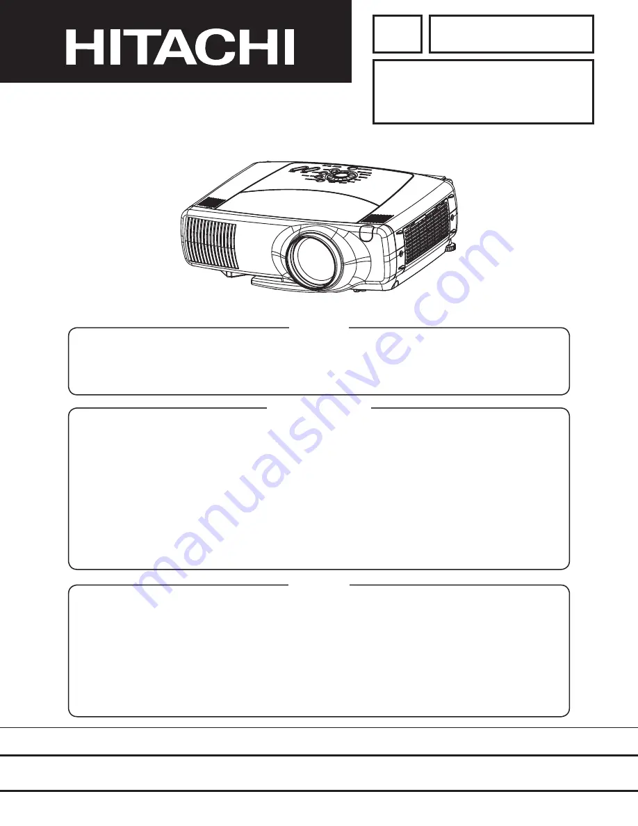
background image

YK

No.0526E

CP-X880

(C8X)

CP-X885

(C8XM)

SPECIFICATIONS AND PARTS ARE SUBJECT TO CHANGE FOR IMPROVEMENT.


Multimedia LCD Projector

November 2002

   Digital Media Division

SERVICE MANUAL

Be sure to read this manual before servicing.  To assure safety from 

fi

 re, electric shock, injury, harmful 

radiation and materials, various measures are provided in this HITACHI Multimedia LCD Projector.  Be 
sure to read cautionary items described in the manual to maintain safety before servicing.

Caution


1. When replace the lamp, to avoid burns to your 

fi

 ngers.  The lamp becomes too hot.

2. Never touch the lamp bulb with a 

fi

 nger or anything else.  Never drop it or give it a shock.  They may 

cause bursting of the bulb.

3. This projector is provided with a high voltage circuit for the lamp.  Do not touch the electric parts of 

power unit (main), when turn on the projector.

4. Do not touch the exhaust fan, during operation.
5. The LCD module assembly is likely to be damaged.  If replacing to the LCD module assembly, do 

not hold the FPC of the LCD module assembly.

6. Use the cables which are included with the projector or speci

fi

 ed.

Service Warning


1.  Features -----------------------------------------------2
2.  Speci

fi

 cations-----------------------------------------2

3.  Names of each part ---------------------------------3
4.  Adjustment --------------------------------------------5
5.  Troubleshooting------------------------------------ 11
6.  Service points -------------------------------------- 16
7.  Wiring diagram ------------------------------------- 31

8.  Disassembly diagram----------------------------- 37
9.  Replacement parts list---------------------------- 39
10.RS-232C communication ------------------------ 40
11.Block diagram -------------------------------------- 46
12.Connector connection diagram ---------------- 47
13.Basic circuit diagram------------------------------ 48

Contents 

Summary of Contents for C8X

Page 1: ...nything else Never drop it or give it a shock They may cause bursting of the bulb 3 This projector is provided with a high voltage circuit for the lamp Do not touch the electric parts of power unit main when turn on the projector 4 Do not touch the exhaust fan during operation 5 The LCD module assembly is likely to be damaged If replacing to the LCD module assembly do not hold the FPC of the LCD m...

Page 2: ...signal TTL level Video Analog 0 7Vp p 75 output impedance positive H V sync TTL level positive negative Composite sync TTL level D sub 15 pin shrink jack 1 0Vp p 75 terminator 0 3Vp p 75 terminator Mini DIN 4 pin jack 200mVrms 57k Stereo mini jack NTSC NTSC4 43 PAL BGDHI SECAM PAL M PAL N PAL60 200mVrms 57k max 3 0Vp p RCA jack 2 1 0Vp p 75 terminator RCA jack 1 0Vp p 75 terminator 0 7Vp p 75 term...

Page 3: ...ONE button TEMP indicator LAMP indicator Lens Remote sensor Lens cap Elevator feet Remote sensor S VIDEO IN port VIDEO IN port DVI port RGB port BNC port AUDIO IN R L port AUDIO IN 1 2 port AUDIO OUT port REMOTE CONTROL port CONTROL port WIRELESS NETWORK MODULE port RGB OUT port USB port COMPONENT VIDEO port Power switch STANDBY ON INPUT KEYSTONE RESET MENU LANP TENP ONE TOUCH RGB BNC DVI VIDEO S ...

Page 4: ...g so may result in malfunction Do not place the remote control near the projector s lens fan or vents Remove the batteries from the remote control and store them in a safe place if you won t be using the remote control for an extended period Replace the batteries whenever the remote control starts to malfunction When strong light such as direct sunlight or light from an extremely close range such ...

Page 5: ...t menu will appear 4 2 Ghost adjustment Signals for internal adjustment 30 30 112 255 0 255 Adjustment procedure 1 Use DAC P GHOST R in the Adjustment menu to adjust so that R color ghost is at a minimum Press the RESET button then raise the value When a ghost appears to the left of a vertical line reduce the value by 2 steps 2 In the same way use DAC P GHOST G in the Adjustment menu to adjust so ...

Page 6: ...s inconspicuous as possible 3 In the same way use DAC P NRSH G in the Adjustment menu to adjust vertical stripes of G color 4 In the same way use DAC P NRSH B in the Adjustment menu to adjust vertical stripes of B color 4 3 Flicker adjustment V COM adjustment Signals for internal adjustment Adjustment procedure 1 Make this adjustment after completing the adjustment in 4 2 Ghost adjustment 2 Use DA...

Page 7: ...28 steps is best 4 Don t adjust GAMMA SUB BRIGHT and G in the Adjust menu Because we want to keep the best contrast ratio 5 Then adjust colors R and B 6 Select GAMMA SUB CONTRAST and G in the Adjust menu If the background is white solid press the ENTER key on the Remote control trasmitter to change to W monochrome in the 28 tone grayscale 7 Adjust GAMMA SUB BRIGHT R and B in the Adjust menu so tha...

Page 8: ...brightness of the entire screen 6 To temporarily turn correction off place the cursor on ON in the Adjust Tone menu and press the key To turn it on again place the cursor on OFF in the Adjust Tone menu and press the key 7 Although this adjustment can also be made using internal signals we will here use the ENTER key on the Remote control transmitter to select the following two signals Solid monoch...

Page 9: ... 2 R and B so that the coordinates are as follows x x1 0 005 y y1 0 010 Target x x1 0 020 y y1 0 050 9 Similarly measure adjustment points No 3 to No 17 and adjust their color coordinates starting in order from the small number points This completes adjustments required for MIN Note Since excessive correction may lead to a correction data overview during internal calculations use the following val...

Page 10: ...st makes it easy to see color shading 7 Next view measurement points No 4 No 5 No 12 No 13 and make similar adjustments 8 Then adjust measurement points No 6 No 7 No 8 No 9 No 14 No 15 No 16 and No 17 This completes the MIN tone adjustments 9 Make similar another three tones as described in steps 1 to 8 above 8 3 16 17 9 11 6 14 2 12 15 13 10 7 4 1 5 8 3 16 17 9 11 14 12 15 13 10 4 1 5 6 2 7 8 3 1...

Page 11: ...ide ES02 EL4332CS IS01 EW01 Parts side E101 Parts side E812 Parts side EV01 Parts side 11 20 10 1 1 3 2 P501 P701 P601 TP98 TP99 TPX29 TPX26 TPX23 TPX20 CHV29 CHV28 CHV34 CHV27 CHV35 CHV36 CHV22 CHV23 TPX19 I104 AP99 Parts side AP98 Parts side S315 IN S314 OUT CHV26 CHV33 I256 Q801 C TH950 PWB assembly Drive PWB assembly Signal PWB assembly Sensor CPC30 low connector ...

Page 12: ... YES Disconnect TSW from Power unit circuit And check TSW short or open PWB assembly Drive Lamp or Power unit ballast Short TSW Open Lights What is the state of LAMP indicator D302 Not light Blinks 1 4 6 12 Is the LAMP connection OK Set the LAMP again Is the voltage at pin and of E807 same NO YES PWB assembly Limit SW PWB assembly Drive Is the LAMP COVER set OK Set the LAMP COVER NG NG 1 2 ...

Page 13: ...PWB assembly Drive fixed to L during warming up L 0V Is E302 PWB assembly Sensor surely connected with PWB assembly Drive by the cable DC FAN Measure the voltage at each pin Set AC to ON and enter standby status The voltage is H 3 3V H 3 3V H 3 3V Measure sure voltage at the of I256 on the PWB assembly Drive Turn on the power supply and check the voltage Check the fan connector connection Connecto...

Page 14: ...the PWB assembly Drive 16 5V 15V 4V 6V E800 E800 E800 E800 1 4 6 12 Power unit circuit NO YES Are voltage input at each pin on the PWB assembly Drive PWB assembly Drive LCD module assembly Are signal input at these pins of EV01 on the PWB assembly Drive Measure the voltage at pin of I104 on the PWB assembly Drive NO YES 0V 5V PWB assembly Drive PWB assembly Signal Check at operating mode CHV29 VID...

Page 15: ...l input at each pin on the PWB assembly Drive CHV26 Audio L CHV33 Audio R Are the signals input at each pin of EV01 on the PWB assembly Drive PWB assembly Signal YES PWB assembly Drive NO CHV22 RX CHV23 TX Pin No RS 232C 1 2 3 6 7 9 10 12 13 14 SEL0 RTS GND RDP TDP Check at operating mode Can not control to RS 232C ...

Page 16: ...e all lead free solder from soldered joints when replacing components If leaded solder should be added to existing lead free joints mix in the leaded solder thoroughly after the lead free solder has been completely melted do not apply the soldering iron without solder Servicing soldering iron A soldering iron with a temperature setting capability temperature control function is recommended The mel...

Page 17: ...sembly Drive Motor lead 6606 CNTH 3054 CNBAR CNPW1 CNPW2 Drive board 6607 6606 CNRM A83 680 CNLC A84 3055 A PWB assembly Drive connector name PWB assembly Drive connection cable name No PWB assembly Drive connection cable name JOINT PWB type and connector PWB assembly Drive connector name Signal content CNPW1 12P PH JA04721 G E72 E800 Power supply secondary CNPW2 3P PH JA04721 B E22 E811 Power sup...

Page 18: ... Remove the optical unit before removing the power supply PWB block When removing the optical unit move it in the direction of the arrow so that the protuberance of the optical unit fan does not become caught in the indentation in the bottom case Use care to avoid applying any stress to the optical unit Bottom case indentation Fan protuberance ...

Page 19: ...irection of the arrow Insert the batteries Align and insert the two AA batteries that came with the projector according to their plus and minus terminals as indicated in the remote control Close the battery cover Replace the battery cover in the direction of the arrow and snap it back into place 2 3 CAUTION Precautions to observe in regards to the batteries Always handle the batteries with care an...

Page 20: ... Do not open the lamp cover while the projector is suspended from above This is dangerous since if the lamp s bulb has broken the shards will fall out when the cover is opened Handle with care jolting or scratching could cause the lamp bulb to burst during use If the replace lamp indicator see Related Messages and Regarding the indicator Lamps comes on replace the lamp as soon as possible Using th...

Page 21: ...n push the point of the lamp cover to fix it as shown in the figure Make sure that the lamp cover does t come up 2 After making sure that the projector has cooled adequately slide the knob of a lamp cover lock as shown in the figure Then one side of the lamp cover is raised Pull up the lamp cover and remove it as shown in the figure 3 Unscrew the 3 screws and slowly pull out the lamp by the handle...

Page 22: ...matically in over 10 minutes 1 Switch power ON and select the LAMP TIME on the OPTION menu 2 Depress the RESET button for at least 3 seconds while lamp time is being displayed The reset menu will then appear 3 Select RESET on the menu with the button and wait until the timer display is cleared NOTE Do not reset the lamp timer without replacing the lamp Reset the lamp timer always when replacing th...

Page 23: ...dealer after confirming the model of your separately sold replacement air filter Replacement air filter model NJ07081 1 Turn off the projector and unplug the power cord Prepare a new air filter one specified for your projector 2 Remove the air filter cover and air filter 4 Turn on the projector power and using the menu reset the filter timer To reset the lamp timer from the OPTION menu select FILT...

Page 24: ... processing To avoid such phenomena AUTO function should be used with the full size picture that has bright tone on its peripheral Note 1 The phenomenon at the failure of AUTO adjustment depends on resolution of input source scene of picture etc 2 There is no failure above in AUTO with video source through VIDEO S VIDEO or COMPONENT input The reason is why recognition of input signal s standard do...

Page 25: ...y code Press the button 3rd entry code Press the KEYSTONE button 4th entry code Press the button Note The Master PIN codes can be used up to 30 times The codes cannot be used thereafter If the Master PIN codes cannot be used see the paragraph of the PIN LOCK system inactivation The PIN LOCK System inactivation 1 When the PIN BOX menu is displayed press RESET for 3 seconds or more in order to get t...

Page 26: ...the screen shown below The menu will close after 10 seconds if there are no further operations 3 Use or to select the usage status number The usage status is as shown below Usage status number see below 0 ON Off LAMP TIME Usage status number 0 Total usage status 1 Current usage status 2 Usage status before first reset 3 Usage status before second reset 8 Usage status before seventh reset Time Numb...

Page 27: ...input signal Please confirm the signal input connection and the status of the signal source SYNC IS OUT OF RANGE ON kHz Hz The horizontal or vertical wavelength of the inputted signal is outside of the response parameters of this unit Please confirm the specs for this unit or the signal source specs CHECK THE AIR FLOW The internal portion temperature is rising Please turn the power OFF and allow t...

Page 28: ... main unit has sufficiently cooled down please make confirmation of the attachment state of the lamp and lamp cover After performing any needed maintenance turn the power ON again The red lamp is lighted or blinks Turned OFF Blinking of the red lamp The cooling fan is not operating Turn the power OFF and wait approximately 20 minutes After the main unit has cooled down please make confirmation tha...

Page 29: ...r 3 seconds 1 Display the menu by the MENU button 2 Select the OPT on the menu 3 Continue pressing the button MAGNIFY OFF for 3 seconds 2 Select the HIGH on the OSD using the button To reset this setup select the NORMAL using the button 3 The OSD will be ended by no operation for 10 seconds or change of input signal To end immediately use one of buttons except buttons NOTE The HIGH mode makes the ...

Page 30: ...PEED FANSPEED SERVICE VIDEO NR yellow selected item LENS MUTE COLOR FILTER TIME same as the menu color white not selected item FILTER TIME ON OFF 2 ON Select the ON on the OSD using button OFF Select the OFF on the OSD using button 3 The OSD will be ended by no operation for 10 seconds or change of input signal To end immediately use one of buttons except buttons ...

Page 31: ...e CNPW2 cable and the TSW cable to circuit power supply board connectors CN102 CN103 and CN104 respectively and check that these cables have been securely connected CNPW1 CNPW2 TSW Pass the CNBAR cable through the ballast holder notch Connect the CNBAR cable to ballast board connector CN2 and check that the cable has been securely connected TAP1 Lay the lamp leads outside the lead groove and bundl...

Page 32: ...e power supply board Lamp lead Lay the lamp leads along the power supply block groove CNBAR CNTH Connect the CNTH cable to sensor board connector E950 3054 lead Power supply board Ballast board CNPWR Connect the CNPWR to connector CN1 and check that the CNPWR is completely locked Power supply board When lapping the ballast board over the power supply board pull the CNPWR cable to the left in the a...

Page 33: ...the optical unit when it is installed PAS5 Pass these 3 cables so they come out of the recess of the fixture encircled in the drawing so they cannot be jammed in the upper cover when it is installed 3054 lead Pull the lamp leads so the ballast parts are not stressed CNPW2 TSW TSW2 CNPW1 Before installing the power supply block clamp the lamp leads to the power supply holder bottom notch with the P...

Page 34: ...G color panel fan 6607 6606 R color panel fan Lamp lead Lay the lamp leads as illustrated so no lead slack can be left and move the lamp leads to the left side of the rib Check the TSW2 model model T90AR1U1N Slide the TSW2 down under the rib Attach the TSW2 with the direction that the model is visible Bottom fan for the lamp 680 PAS2 Fold the 680 fan lead 3 or 4 times and bundle and clamp the fold...

Page 35: ...or E302 Connect the 3054 fan lead to connector E809 Connect the CNBAR cable to connector E805 Connect the CNPW1 cable to connector E800 Connect the CNPW2 cable to connector E811 4 Wiring for Drive Board Installation Connect the fan 680 lead to connector E808 680 CNLC Connect the CNLC cable to connector E807 A84 Connect the A 84 speaker lead to connector ESPR Pass the lead through the hook on the b...

Page 36: ... cable surplus under the drive board so they cannot be jammed in the upper case when it is installed Lay these cables inside the bosses and the rib on the ballast holder Boss Boss Rib Push the 680 lead surplus and the PAS2 under the drive board Check that the peripheral cables are kept away from the lamp holder since the lamp cannot be replaced if any one of the peripheral cables is laid on the la...

Page 37: ...o scratch front foot ass y by this screw Pull out front foot ass y before screwing Front foot ass y 3 10 DT SILVER M3 6 LOCK M3 8 WASHER T3 12 T3 12 T3 12 T3 16 T3 12 M3 10 DP M3 8 T3 12 M3 10 DT SILVER M3 10 DT SILVER M3 10 DT SILVER M3 10 DT SILVER M3 82 M3 10 DT SILVER T3 10 M3 6 LOCK T3 12 T3 12 T3 12 T2 5 T3 12 ...

Page 38: ... X880 CP X885 38 M2 3 8 T3 32 T3 10 BLACK T3 10 BLACK 20 35 35 36 5 22 25 11 12 3 29 37 37 24 23 19 18 19 32 8 M3 10 WASHER M3 10 WASHER T3 12 T3 12 M2 6 6 M3 25 T3 12 T3 12 P T3 16 T3 12 P T3 12 P M2 6 6 ...

Page 39: ...AP HL01881 REMOTE CONTROL UNIT 22 HA01151 POWER UNIT BALLAST NX05741 CLEANING TOOL FOR DUST 23 JP06045 PWB ASS Y SENSOR NX05742 COTTON STICK L70 24 2722449 FUSE 8A QR54471 INSTRUCTION MANUAL 25 HA01111 POWER UNIT CIRCUIT 26 JP06038 PWB ASS Y REMOTE CONTROL CP X885 SYMBOL PARTS SYMBOL PARTS NO NO DESCRIPTION NO NO DESCRIPTION 1 QD35161 UPPER CASE ASS Y 27 JP06042 PWB ASS Y SIGNAL 2 GK00831 SPEAKER ...

Page 40: ...Header BE EF 03 06 00 CRC_low CRC_high CRC_low Lower byte of CRC flag for command data CRC_high Upper byte of CRC flag for command data 3 Command data Command data chart byte_0 byte_1 Action low high byte_2 byte_3 Type low high byte_4 byte_5 Setting code low high Action Classification Content Action byte_0 1 1 SET Change setting to desired value 2 GET Read projector internal setup value 4 INCREMEN...

Page 41: ...ng the projector setting value Decrement command 1 The computer sends the decrement code Header Command data 05H 00H type 2 bytes 00H 00H to the projector 2 The projector decreases the setting value on the above setting code 3 The projector returns the response code 06H to the computer When a command sent by the projector cannot be understood by the computer When the command sent by the projector ...

Page 42: ... 30 20 00 Get BE EF 03 06 00 38 D2 02 00 04 30 00 00 Language Set English BE EF 03 06 00 F7 D3 01 00 05 30 00 00 Français BE EF 03 06 00 67 D2 01 00 05 30 01 00 Deutsch BE EF 03 06 00 97 D2 01 00 05 30 02 00 Español BE EF 03 06 00 07 D3 01 00 05 30 03 00 Italiano BE EF 03 06 00 37 D1 01 00 05 30 04 00 Norsk BE EF 03 06 00 A7 D0 01 00 05 30 05 00 Nederlands BE EF 03 06 00 57 D0 01 00 05 30 06 00 Po...

Page 43: ...rror 04 00 05 00 06 00 07 00 08 00 Temp error Air flow error Lamp Time over Cool error Filter Error Power Set OFF BE EF 03 06 00 2A D3 01 00 00 60 00 00 ON BE EF 03 06 00 BA D2 01 00 00 60 01 00 Get BE EF 03 06 00 19 D3 02 00 00 60 00 00 Input Source Set RGB BE EF 03 06 00 FE D2 01 00 00 20 00 00 RGB BE EF 03 06 00 3E D0 01 00 00 20 04 00 Video BE EF 03 06 00 6E D3 01 00 00 20 01 00 S Video BE EF ...

Page 44: ...3 05 00 01 21 00 00 H Size Get BE EF 03 06 00 B5 82 02 00 02 21 00 00 Increment BE EF 03 06 00 D3 82 04 00 02 21 00 00 Decrement BE EF 03 06 00 02 83 05 00 02 21 00 00 H Phase Get BE EF 03 06 00 49 83 02 00 03 21 00 00 Increment BE EF 03 06 00 2F 83 04 00 03 21 00 00 Decrement BE EF 03 06 00 FE 82 05 00 03 21 00 00 Sharpness Get BE EF 03 06 00 F1 72 02 00 01 22 00 00 Increment BE EF 03 06 00 97 72...

Page 45: ...0 Get BE EF 03 06 00 08 23 02 00 00 33 00 00 GAMMA Set NORMAL BE EF 03 06 00 C7 F0 01 00 A1 30 00 00 CINEMA BE EF 03 06 00 57 F1 01 00 A1 30 01 00 DYNAMIC BE EF 03 06 00 A7 F1 01 00 A1 30 02 00 Get BE EF 03 06 00 F4 F0 02 00 A1 30 00 00 Over Scan Set Large BE EF 03 06 00 C2 71 01 00 09 22 02 00 Middle BE EF 03 06 00 32 71 01 00 09 22 01 00 Small BE EF 03 06 00 A2 70 01 00 09 22 00 00 Get BE EF 03 ...

Page 46: ...DRIVE PWB AC INPUT Flash ROM OPTICAL UNIT PROJECTION LENS Lamp SRAM EEPROM COLOR UNIFORMITY TIMING GENERATOR LEVEL SHIFTER ADC Input SIGNAL PWB X tal 䌄䌃 䌐䌏䌗䌅䌒 䌒䌅䌇䌕䌒䌁䌔䌏䌒 0 99 1 3 XGA LCD PANEL MOTOR DAC P S PLL Image_PROCESSOR MAIN CPU S H FAN OPTICAL ENGINE Block diagram C8X C8XM ...

Page 47: ...2 LOUT 18 GND 3 26 LCCOM 19 RGB G 4 27 DIRY SPEAKER 20 GND 5 28 VSSY 21 GND 6 29 DY ESPR RGB IN ES01 22 RGB B 7 30 MON 1 ROUT 23 GND 8 2 ROUT 24 GND 9 BNC IN ES02 25 RGB H INV 10 SPEAKER 26 RGB V INV 11 27 RGB1 2 12 E807 E941 28 5VST 13 1 OUT 1 PWB 29 5VST 14 2 COVER 2 assembly RGB OUT ES03 30 GND 15 SWITCH 1 GND 16 2 5VST 17 CONTROL EM01 3 5VST 18 E804 4 R1 R2 19 1 FAN4S FAN 5 RGB V INV 20 2 OUT ...

Page 48: ...0 CP X885 48 13 Basic circuit diagram Parts with hatching are not mounted 6 5 4 3 2 1 6 5 4 3 2 1 E D C B A PWB assembly LIMIT SWITCH C8X C8XM PWB assembly SENSOR C8X C8XM PWB assembly REMOTE CONTROL C8X C8XM ...

Page 49: ...6 5 4 3 2 1 6 5 4 3 2 1 A B C D E F G POWER UNIT BALLAST C8X C8XM ...

Page 50: ...6 5 4 3 2 1 6 5 4 3 2 1 A B C D E F G Out put connector POWER UNIT CIRCUIT C8X C8XM ...

Page 51: ...1 2 3 4 5 6 6 1 2 3 4 5 D A B C E F G PWB assembly DRIVE 1 C8X C8XM ...

Page 52: ...1 2 3 4 5 6 6 1 2 3 4 5 D A B C E F G PWB assembly DRIVE 2 C8X C8XM ...

Page 53: ...1 2 3 4 5 6 6 1 2 3 4 5 D A B C E F G PWB assembly DRIVE 3 C8X C8XM ...

Page 54: ...1 2 3 4 5 6 6 1 2 3 4 5 D A B C E F G PWB assembly DRIVE 4 C8X C8XM ...

Page 55: ...1 2 3 4 5 6 6 1 2 3 4 5 D A B C E F G PWB assembly DRIVE 5 C8X C8XM ...

Page 56: ...1 2 3 4 5 6 6 1 2 3 4 5 D A B C E F G PWB assembly DRIVE 6 C8X C8XM ...

Page 57: ...1 2 3 4 5 6 6 1 2 3 4 5 D A B C E F G PWB assembly DRIVE 7 C8X C8XM ...

Page 58: ...1 2 3 4 5 6 6 1 2 3 4 5 D A B C E F G PWB assembly DRIVE 8 C8X C8XM ...

Page 59: ...1 2 3 4 5 6 6 1 2 3 4 5 D A B C E F G PWB assembly DRIVE 9 C8X C8XM ...

Page 60: ...1 2 3 4 5 6 6 1 2 3 4 5 D A B C E F G PWB assembly DRIVE 10 C8X C8XM ...

Page 61: ...1 2 3 4 5 6 6 1 2 3 4 5 D A B C E F G PWB assembly DRIVE 11 C8X C8XM ...

Page 62: ...1 2 3 4 5 6 6 1 2 3 4 5 D A B C E F G PWB assembly DRIVE 12 C8X C8XM ...

Page 63: ...1 2 3 4 5 6 6 1 2 3 4 5 D A B C E F G PWB assembly DRIVE 13 C8X C8XM ...

Page 64: ...1 2 3 4 5 6 6 1 2 3 4 5 D A B C E F G PWB assembly SIGNAL 1 C8X C8XM ...

Page 65: ...1 2 3 4 5 6 6 1 2 3 4 5 D A B C E F G PWB assembly SIGNAL 2 C8X C8XM ...

Page 66: ...1 2 3 4 5 6 6 1 2 3 4 5 D A B C E F G PWB assembly SIGNAL 3 C8X C8XM ...

Page 67: ...embly DRIVE 2 PWB assembly DRIVE 3 PWB assembly DRIVE 4 PWB assembly DRIVE 5 PWB assembly DRIVE 6 PWB assembly DRIVE 7 PWB assembly DRIVE 8 PWB assembly DRIVE 9 PWB assembly DRIVE 10 PWB assembly DRIVE 11 PWB assembly DRIVE 12 PWB assembly DRIVE 13 PWB assembly SIGNAL 1 PWB assembly SIGNAL 2 PWB assembly SIGNAL 3 Basic circuit diagram List ...

Page 68: ...CP X880 YK No 0526E Digital Media Division CP X885 QR54041 Printed in Japan S ...

Reviews: