background image

SPECIFICATIONS AND PARTS ARE SUBJECT TO CHANGE FOR IMPROVEMENT.


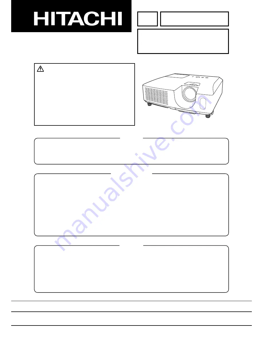
Multimedia LCD Projector


July  2009

YK

No.0628E

CP-RX78

(C15-20EE)

SERVICE MANUAL

Be sure to read this manual before servicing.  To assure safety from 

fi

 re, electric shock, injury, harmful 

radiation and materials, various measures are provided in this Hitachi Multimedia LCD Projector.
Be sure to read cautionary items described in the manual to maintain safety before servicing.

Caution


1. When replace the lamp, to avoid burns to your 

fi

 ngers.  The lamp becomes too hot.

2. Never touch the lamp bulb with a 

fi

 nger or anything else.  Never drop it or give it a shock.  They may 

cause bursting of the bulb.

3. This projector is provided with a high voltage circuit for the lamp.  Do not touch the electric parts of 

power unit (circuit) and power unit (ballast), after turn on the projector.

4. Do not touch the exhaust fan, during operation.
5. The LCD module assembly is likely to be damaged.  If replacing to the LCD PRISM assembly, do 

not hold the FPC of the LCD module assembly.

6. Use the cables which are included with the projector or speci

fi

 ed.

Service Warning


Warning

The technical information and parts shown in this 
manual are not to be used for: the development, 
design, production, storage or use of nuclear, chemical,   
biological or missile weapons or other weapons of 
mass destruction; or military purposes; or purposes that 
endanger global safety and peace. Moreover, do not 
sell, give, or export these items, or grant permission for 
use to parties with such objectives. Forward all inquiries 
to Hitachi Consumer Electronics Co., Ltd.

1. Features ------------------------------------------------------ 2
2. Speci

fi

 cations ----------------------------------------------- 2

3.  Names of each part ---------------------------------------- 3
4. Adjustment --------------------------------------------------- 4
5. Troubleshooting ------------------------------------------ 10
6. Service points --------------------------------------------- 14
7. Wiring diagram 

-------------------------------------------- 30

8. Disassembly diagram ----------------------------------- 36
9. Replacement parts list ---------------------------------- 45
10. Block  diagram --------------------------------------------- 46
11. Connector connection diagram ----------------------- 47
12. Basic  circuit  diagram  ------------------------------------ 48

Contents 

Summary of Contents for C15-20EE

Page 1: ...rojector 4 Do not touch the exhaust fan during operation 5 The LCD module assembly is likely to be damaged If replacing to the LCD PRISM assembly do not hold the FPC of the LCD module assembly 6 Use the cables which are included with the projector or specified Service Warning Warning The technical information and parts shown in this manual are not to be used for the development design production s...

Page 2: ...omputer IN Video signal Y Analog 1 0 0 1Vp p with composite sync 75Ω terminated Cb Pb Analog 0 7 0 1Vp p 75Ω terminated Cr Pr Analog 0 7 0 1Vp p 75Ω terminated System 480i 60 480p 60 576i 50 720p 50 60 1080i 50 60 VIDEO signal VIDEO IN 1 0Vp p 75Ω termination Power supply AC100 120V 3 0A AC220 240V 1 5A Power consumption 250W Dimensions 317 W x 98 H x 288 D mm Not including protruding parts Weight...

Page 3: ...button 2 INPUT button 3 MENU button It consists of four cursor buttons 4 POWER indicator 5 TEMP indicator 6 LAMP indicator Rear panel 1 COMPUTER IN port 2 Shutdown switch 3 VIDEO port Use the shutdown switch only when the projector is not turned off by normal procedure since pushing this switch stops operation of the projector without cooling it down CAUTION 1 2 3 1 3 2 4 6 5 Remote control 1 VIDE...

Page 4: ...NU button to display the EASY menu If Advanced menu comes up move to the Easy menu Select the RESET in the EASY menu and press the or ENTER button to open the RESET dia log Choose the EXECUTE with the button Note that the projector will not allow you to reset its adjustment values with no signal input 4 Perform all adjustments from the FACTORY MENU Operate as follows to display the FAC TORY MENU W...

Page 5: ...o that the flicker at the center of the screen is less than the flicker at the periphery When the flicker is about the same across the whole screen adjust so that the flicker at the center of the screen is somewhat less than elsewhere 2 In the same way use DAC P V COM G in the FACTORY MENU to adjust the G color flicker 3 In the same way use DAC P V COM B in the FACTORY MENU to adjust the B color f...

Page 6: ...TORY MENU If the background is white solid press the ENTER key on the remote control to change to W monochrome in the 33 tone grayscale 7 Adjust GAMMA SUB BRT R and B in the FACTORY MENU so that low brightness white balance is best 8 Adjust GAMMA SUB CNT R and B in the FACTORY MENU so that middle brightness white balance is best 9 Repeat steps 7 to 8 above and adjust so that brightness white balan...

Page 7: ...e color uniformity of the entire screen can be adjusted by adjusting the white balance for each of the points starting in order from the low numbers 5 Adjustment point No 1 should not be adjusted because it controls the brightness of the entire screen 6 To temporarily turn correction off place the cur sor on C UNIF in the Adjust Tone menu and press the key The ON OFF menu appears Place the cursor ...

Page 8: ...pletes adjustments required for MID 1 Note Since excessive correction may lead to a correction data overview during internal calculations use the following values for reference No 2 to No 5 40 or less No 6 to No 9 50 or less No 10 to No 13 70 or less No 14 to No 17 120 or less 10 Then adjust the MIN tone G so that the ad justment values are two times as much as MID 1 tone G values This completes G...

Page 9: ...lor shading 7 Next view measurement points No 4 No 5 No 12 No 13 and make similar adjustments 8 Then adjust measurement points No 6 No 7 No 8 No 9 No 14 No 15 No 16 and No 17 This completes the MIN tone adjustments 9 Make similar adjustments for other tones ex cept the MID 4 and MID 6 tones as de scribed in steps 1 to 8 above 8 3 16 17 9 11 6 14 2 12 15 13 10 7 4 1 5 8 3 16 17 9 11 14 12 15 13 10 ...

Page 10: ...ting Check points E302 S801 E301 E805 E807 E814 E802 E800 E801 E806 P501 P601 P701 TSW IS02 CHV1C CHH1C Note Dotted outlines in the picture above show components behind a metallic part earth metal or on the back side of the main board ...

Page 11: ...d before measuring resistance Measure resistance between pins 1 and 3 of E800 Disconnect TSW from power unit circuit and measure resistance of TSW Open 0Ω PWB assembly MAIN Power unit circuit Thermal switch TSW Open Power unit circuit NO Measure resistance between pins 9 and 17 and between pins 5 and 6 of E800 0Ω PWB assembly MAIN Power unit circuit Power unit circuit Open Go to the next page YES ...

Page 12: ... during warming up Not light and blink PWB assembly MAIN YES L 0V Power unit ballast No Are the voltage supplied to the pin 2 of connectors for DC fans soon after the button is pressed Observe the voltage waveforms at pin 1 of connectors for DC fans soon after the button is pressed Blinks DC fan failed in above check Correct waveform is drawn below f 40Hz PWB assembly MAIN NO 0V PWB assembly MAIN ...

Page 13: ...nels connection to the MAIN board No CPC40 connector PWB assembly MAIN LCD prism assembly OK NG SN74LV14APW IS02 PWB assembly MAIN NG Picture is not displayed when the Video signal is input Are the splash screen and the user menu displayed correctly YES Confirm the LCD Panels connection to the MAIN board No CPC40 connector PWB assembly MAIN LCD prism assembly OK NG PWB assembly MAIN CHH1C H sync i...

Page 14: ...ts mix in the leaded solder thoroughly after the lead free solder has been completely melted do not apply the soldering iron without solder Servicing soldering iron A soldering iron with a temperature setting capability temperature control function is recommended The melting point of lead free solder is higher than leaded solder Use a soldering iron that maintains a high stable temperature large h...

Page 15: ...eaning P NX32451 Cotton stick BB 014 2 Air duster Dust blower spray can 3 Vacuum cleaner 2 Disassemble and setting up 1 Turn off the projector and unplug the power cord 2 Remove the lamp cover and upper case according to the disassembling diagram of chapter 8 6 3 Cleaning up dust from panels and optical filters WARNING Wear sunglasses to protect your eyes when you maintain the projector with its l...

Page 16: ...ke it free 4 Press and hold the switch S801 using an insulator during maintenance 5 Keep the unscrewed wires away from all of electric parts WARNING Never put the heavy stress to the main board Otherwise connectors will be damaged Remove these screws Flexible cables of LCD panel Remove there screws ...

Page 17: ... check the dust on screen While removing the dust separated dust will be blown off by air cooling system Please pay attention not to damage panels and optical filters Bend the top of SWAB a little if it is hard to insert the SWAB Panel Holder Optical filter 5 Re assembly 1 Turn off the set and unplug the power cord 2 Remove an insulator from S801 3 Screw down the PWB assembly MAIN and connect the ...

Page 18: ...he signal setting for the projector s remote sensor Switch between Setting 1 and 2 using the SERVICE REMOTE FREQ item found in OPTION MENU Use the button to change the Projector s remote sensor setting 1 NORMAL 2 HIGH Items with a checkmark are on The factory default setting is for both 1 NORMAL and 2 HIGH to be on If the remote control does not function correctly set this to either only 1 or only...

Page 19: ...he EASY MENU 1 Press the MENU button to display a menu 2 Point at the FILTER TIME using the button then press the button A dialog will appear 3 Press the button to select OK on the dialog It performs resetting the filter time Before taking care of the air filter make sure the power cable is not plugged in then allow the projector to cool sufficiently Taking care of the air filter in a high temperature...

Page 20: ...ents or get it in your eyes or mouth Before replacing the lamp turn the projector off and unplug the power cord then wait at least 45 minutes for the lamp to cool sufficiently Handling the lamp while hot can cause burns as well as damaging the lamp Never unscrew except the appointed marked by an arrow screws Do not open the lamp cover while the projector is suspended from above This is dangerous s...

Page 21: ...ews of the lamp that are loosened in the previous process to lock it in place 6 While putting the interlocking parts of the lamp cover and the projector together slide the lamp cover back in place Then firmly fasten the screw of the lamp cover 7 Turn the projector on and reset the lamp time using the LAMP TIME item in the OPTION menu Replacing the lamp 4 Point at the LAMP TIME using the button then...

Page 22: ...e of the projector In order to ensure the safe use of the projector it needs to clean and inspect the projector about once a year Caring for the lens If the lens is flawed soiled or fogged it could cause deterioration of display quality Please take care of the lens being cautions of the handling 1 Turn the projector off and unplug the power cord Allow the projector to cool sufficiently 2 After mak...

Page 23: ...nomena AUTO function should be used with the full size picture that has bright tone on its peripheral Note 1 The phenomenon at the failure of AUTO adjustment depends on resolution of input source scene of picture etc 2 There is no failure above in AUTO with video source through VIDEO S VIDEO or COMPONENT input The reason is why recognition of input signal s standard does not need to search the cap...

Page 24: ...splayed by pressing the MENU button remote or button keypad when Transition Detector Alarm is displayed 2 Press the Magnify off button once then press Magnify off button of remote for 3 second or more to dis play SERVICE PASSWORD box 3 Enter the Life Key MENU KEYSTONE Then all security functions will be inactivated temporarily Note The Life key can be used up to 30 times The key cannot be used the...

Page 25: ...button 4th entry code Press the button Note The Master PIN codes can be used up to 30 times The codes cannot be used thereafter If the Master PIN codes cannot be used see the paragraph of the PIN LOCK system inactivation The PIN LOCK System inactivation 1 When the PIN BOX menu is displayed press RESET for 3 seconds or more in order to get the ID Inquir ing Code PIN BOX ID Inquiring Code 2 Send HIT...

Page 26: ...ce specs An improper signal is input Please confirm the specs for your projector or the signal source specs The internal temperature is rising Please turn the power off and allow the projector to cool down at least 20 minutes After having confirmed the following items please turn the power ON again Is there blockage of the air passage aperture Is the air filter dirty Does the peripheral temperature e...

Page 27: ...tter has become caught in the fan etc and then turn the power on again If the same indication is displayed after the remedy please replace a fan Blinking In Red or Lighting In Red Turned off Lighting In Red There is a possibility that the interior portion has become heated Please turn the power off and allow the unit to cool down at least 20 minutes After the projector has sufficiently cooled down...

Page 28: ...te control button operation mode NORMAR LONG The LONG allows to control the projector with the remote control unit when you hold a button of it for about 3seconds and makes MY BUTTON 1 2 function as LONG KEY DISABLE LONG KEY ENABLE compulsorily If you use these buttons to control the projector as you assigned with the MY BUTTON menu set to the NORMAL SOFT RESET If this is executed all of the user ...

Page 29: ...appear Keypad Press the down button and then hold the down button together with INPUT button for about 3seconds Remote control Press the MAGNIFY OFF button and then hold the MAGNIFY OFF button for about 3seconds 3 Align the blue red image with the green image using the HR HB VR and VB HR shifts the red image to the left right HB shifts the blue image to the left right VR shifts the red image upwar...

Page 30: ...n the housing and the SK binder and so that the claw is placed in the housing side Be sure to lock the claw FE1 Housing SK binder Claw CNGD1 Fasten the end of CNGD1 to the Power metal with the screw TSW Check the marking of TSW UP62 UCHIYA The circuit board of Circuit unit must be a silk screen printings in green CNTS Connect CNTS here Connect the CNBAR here Connect the CNLAP here until it clicks ...

Page 31: ... units with CNPFC 2 Wire CNTS CNLAP and CNGD1 out of the power unit block 3 Secure E2 CNTS and CNBAR Connect the CNPFC cable to the ballast power board with a click Pass the CNPFC through this hole of the insulating sheet Bend the CNPFC too the inside so that the CNPFC cannot touch the metallic casing power shield metal Area of Importance Do not loosen the CNLAP in order to prevent it from touchin...

Page 32: ... L 20mm Stick it about 50mm away form the hook Put the 3010 cable into this slit and style it with no excessive length th so that it will not be pinched into the fan After attaching the panel duct Before attaching the panel duct Put the cables into the hooks Fasten the E1 temp sensor underneath the panel duct with a screw Fix the CNRC into the slits on the left hand and the E1 and 3020 into the sl...

Page 33: ...pinched between the upper case and the bottom case Wire the CNTS and the CNLAP so that they do not protrude from the line drawn on the screw in the diagram to the right side since the boss will come to the area shown in the diagram when you attach the upper case Pass the CNTS behind the CNLAP and style them so that they do not protrude from the bottom case Boss will come to this area Screw Cross s...

Page 34: ...AR Connect the 3010 Connect the 3030 E2 E2 Pass the E2 and the 3030 on the right side of the CNPW Otherwise the earth metal will pinch the wires Connect the CNBAR Confirm that there are no excessive lengths of CNTS CNBAR and E2 cables Area of Importance Pass the CNBAR CNTS and 3030 through this hook Be sure to put the CNBAR and the 3030 into the hook before the CNTS so that the CNTS prevents the o...

Page 35: ...3000 Slide the stopper to lock the B panel flexible cable Close the stopper to lock the G panel flexible cable Slide the stopper to lock the R panel flexible cable Put the excessive lengths on the main board Insert panel flexible cables Put the excessive length under the main board Do not let the cables protrude from the outline of the bottom case ...

Page 36: ...78 C15 20EE 8 Disassembly diagram 3 2 1 13 17 16 12 15 24 PWB assembly MAIN Terminal Remove UPPER CASE PWB assembly MAIN Remove LAMP DICHROIC OPTICS UNIT LENS SPEAKER reverse side Continued on next page 25 6 19 ...

Page 37: ...37 CP RX78 C15 20EE 9 9 8 14 2 10 5 5 4 11 23 7 20 21 Remove DUCT FAN Remove PANEL DUCT FAN FILTER Remove POWER UNIT BLOCK FOOT Remove POWER UNIT BALLAST CIRCUIT ...

Page 38: ... upper case when disassembling the machine If the upper case is detached with the lamp door installed the MAIN board might be damaged a Remove the Lamp door Loosen this screw b Remove 8 screws on the bottom and 2 screws on the rear to detach the upper case 2 screws CAUTION This is not a screw hole Do NOT insert a screw or screwdriver into it to avoid damaging the inside 8 screws Lamp door ...

Page 39: ...d the bottom cases tighten these screws while pressing down the upper case in the direction of the arrow Be careful not to bend the outside casing Torque 0 39 0 59N m When assembling b Attach the Lamp door CAUTION This is not a screw hole Do NOT insert a screw or screwdriver into it to avoid damaging the in side CAUTION Tighten this screw using a manual screwdriver 2 screws Lamp door ...

Page 40: ...from MAIN board and rear panel Remove this screw Dettaching the MAIN board or INPUT board CAUTION Never swing the screwdriver while you loosen this screw Otherwise the I O metal will change Flexible cables of LCD panel Remove there screws ...

Page 41: ...d CAUTION Tighten this screw with the CNGD1 cable Never swing the screwdriver while you tighten this screw Otherwise the I O metal will change Screw down the MAIN board together with the F guard earth metal Attach the F guard earth metal so that the fan guard and the lib of the lamp house come into the part of the F guard earth metal directed by the arrow F guard Earth metal Lib lamp house Fan gua...

Page 42: ...he LCD prism assembly Attaching detaching the LCD prism assembly CAUTION Please handle the LCD prism assembly with care in order not to make the convergence worse Pinch the projection of a top of the LCD prism assembly tightly and lift it up carefully when removing it Never let the LCD prism assembly touch any other parts Screws ...

Page 43: ...r the hook makes the work hard Therefore use a tool like a screwdriver to unhook it Pnel duct Rib Detach and attach the lens assembly In some of the projectors a few of metallic spacers are installed between the lens assembly and the dichroic optics unit Never detach the lens assembly except when you replace it because the spacers will come off Don t put back the spacers used in the original optic...

Page 44: ...ew than the original the screw might touch the electric parts inside the power unit and short circuit or dielectric breakdown would be caused 3 Replacement of Ballast power unit Insert the end of the insulatng sheet into the slit of the ballast power board before you attach the ballast power board to the power unit casing Put the power shield metal inside the bottom case when attaching the power u...

Page 45: ...OL BUTTON C15 22 NJ26302 AIR FILTER ASS Y S C 15 3 QD65971 LAMP DOOR ASS Y C15 23 FH00442 THERMAL SWITCH ASS Y 4 QD66006 BOTTOM CASE EN EN ASS Y 24 KQ06052 LENS ASS Y C15 EN 5 QJ05871 ADJUST FOOT ASS Y C15 25 DT01022 C15 EN OP LAMP UNIT AS 6 MJ02872 D SUB SCREW 26 QD66031 FILTER COVER C15 7 AZ00257 TERMISTOR B 8 AZ00253 THERMISTOR A 9 GS01671 DC FAN SF8028H ZH3P L341 10 GS01341 DC FAN BM6025 11 GS...

Page 46: ...46 CP RX78 C15 20EE 10 Block diagram VIDEO ...

Page 47: ...47 CP RX78 C15 20EE 11 Connector connection diagram ...

Page 48: ...005 100p C 1 2 1005 R012 100 1 2 I002 KSM 2003LM2EL 1 Vout 2 GND 3 VCC C002 1005 100p C 1 2 1005 R002 100 1 2 C003 47 6 3 MVK SKV 1 2 2125 R001 47 1 2 I001 KSM 2003LM2EL 1 Vout 2 GND 3 VCC APRC01 1 APRC02 1 APRC03 1 C011 1 0 10 1 2 APRC04 1 C001 1 0 10 1 2 E002 502386 4H 1 2 3 4 G1 G2 5V VCC REMOTE1 GND 56 9KHz UP DOWN REMOTE2 PWB assembly REMOTE ...

Page 49: ...CP RX78 C15 20EE 1 2 3 4 5 6 1 2 3 4 5 6 A B C D E F G POWER UNIT BALLAST 1 CONFIDENTIAL ...

Page 50: ...CP RX78 C15 20EE 1 2 3 4 5 6 1 2 3 4 5 6 A B C D E F G POWER UNIT BALLAST 2 CONFIDENTIAL ...

Page 51: ...CP RX78 C15 20EE 1 2 3 4 5 6 1 2 3 4 5 6 A B C D E F G POWER UNIT CIRCUIT CONFIDENTIAL ...

Page 52: ...CP RX78 C15 20EE 1 2 3 4 5 6 1 2 3 4 5 6 A B C D E F G PWB assembly MAIN 1 CONFIDENTIAL ...

Page 53: ... RESETB AD9 EXTRSTEN AF10 ADR24B AD8 TRSTN AC20 EXTMCLK AD17 EXTINT0 AE18 EXTINT1 AB8 TESTMODE0 AA8 TESTMODE1 AF8 TESTMODE2 AF7 VSS AD16 RD AF17 WR AC19 ROMOE AE17 ROMWE AF18 CS0 AD18 CS1 AE26 NMI AC15 A1 AE16 A2 AF16 A3 AC16 A4 AD15 A5 AE15 A6 AC14 A7 AF15 A8 AD14 A9 AC12 A10 AE14 A11 AC13 A12 AF14 A13 AD13 A14 AE13 A15 AF13 A16 AC10 A17 AC11 A18 AD12 A19 AE12 A20 AF12 A21 AC9 A22 AD10 A23 AE24 D...

Page 54: ...CP RX78 C15 20EE 1 2 3 4 5 6 1 2 3 4 5 6 A B C D E F G PWB assembly MAIN 3 CONFIDENTIAL ...

Page 55: ...CP RX78 C15 20EE 1 2 3 4 5 6 1 2 3 4 5 6 A B C D E F G PWB assembly MAIN 4 CONFIDENTIAL ...

Page 56: ...SA3 L4 VSSA1 AB22 VSS AB22 AB21 VSS AB21 AB11 VSS AB11 AB2 VSS AB2 AB1 VSS AB1 AA22 VSS AA22 AA11 VSS AA11 AA10 VSS AA10 AA1 VSS AA1 Y12 VSS Y12 Y11 VSS Y11 Y10 VSS Y10 P14 VSS P14 P13 VSS P13 P12 VSS P12 P11 VSS P11 P10 VSS P10 P9 VSS P9 N14 VSS N14 N13 VSS N13 N12 VSS N12 N11 VSS N11 N10 VSS N10 N9 VSS N9 M22 VSS M22 M21 VSS M21 M20 VSS M20 M14 VSS M14 M13 VSS M13 M12 VSS M12 M11 VSS M11 M10 VSS...

Page 57: ...5 6 7 8 9 10 11 12 13 14 15 16 17 18 19 20 21 22 23 24 25 26 27 28 29 30 31 32 33 34 35 36 37 38 39 40 G1 G2 I501 CXA7009R DB_IN1 DB_IN0 VDD 3 DGND 4 DGND 5 RET DIRC SCL SDA XCLR ADDR0 ADDR1 ADDR2 AGND 14 REF_IN VCC 16 REF_OUT AGND 18 VCOM_OUT PGND 20 PVCC 21 SIG_OUT12 SIG_OUT11 PGND 24 SIG_OUT10 SIG_OUT9 PVCC 27 SIG_OUT8 SIG_OUT7 PGND 30 SIG_OUT6 SIG_OUT5 PVCC 33 SIG_OUT4 SIG_OUT3 PGND 36 SIG_OUT...

Page 58: ..._OUT12 SIG_OUT11 PGND 24 SIG_OUT10 SIG_OUT9 PVCC 27 SIG_OUT8 SIG_OUT7 PGND 30 SIG_OUT6 SIG_OUT5 PVCC 33 SIG_OUT4 SIG_OUT3 PGND 36 SIG_OUT2 SIG_OUT1 PVCC 39 SID_OUT PGND 41 CAL_OUT PVCC 43 CAL_IN VCC 45 AGND 46 DGND 47 GCFB_I GCFB_O VDDMNT SHT_I SHT_O FRP VD PRG CLK VDD 57 DGND 58 DA_IN11 DA_IN10 DA_IN9 DA_IN8 DA_IN7 DA_IN6 DA_IN5 DA_IN4 DA_IN3 DA_IN2 DA_IN1 DA_IN0 DB_IN11 DB_IN10 DB_IN9 DB_IN8 DB_...

Page 59: ...DCK3_B BD1 1 C710 1005 0 1 10 1 2 C752 0 1 25 1 2 APB09 1 APB01 1 BD2 0 BD1 2 BD1 0 APB23 1 C755 0 1 25 1 2 C707 0 1 25 1 2 1005 R741 1 0k 1 2 BD2 10 R736 2 2 1 2 APB39 1 APB20 1 APB08 1 VD APB25 1 1005 R731 10 1 2 C754 0 1 25 1 2 I2CDATP 1005 R701 0 1 2 APB38 1 SCAN C751 10 16 MVK SKV 1 2 1005 R733 3 3k 1 2 ENB C705 0 1 25 1 2 BD2 1 BD2 6 3 3VP 1005 R721 4 7k 1 2 APB11 1 I701 CXA7009R DB_IN1 DB_I...

Page 60: ...CP RX78 C15 20EE 1 2 3 4 5 6 1 2 3 4 5 6 A B C D E F G PWB assembly MAIN 9 CONFIDENTIAL ...

Page 61: ...CP RX78 C15 20EE 1 2 3 4 5 6 1 2 3 4 5 6 A B C D E F G PWB assembly MAIN 10 CONFIDENTIAL ...

Page 62: ...CP RX78 C15 20EE 1 2 3 4 5 6 1 2 3 4 5 6 A B C D E F G PWB assembly MAIN 11 CONFIDENTIAL ...

Page 63: ...CP RX78 C15 20EE 1 2 3 4 5 6 1 2 3 4 5 6 A B C D E F G PWB assembly MAIN 12 CONFIDENTIAL ...

Page 64: ...CP RX78 C15 20EE 1 2 3 4 5 6 1 2 3 4 5 6 A B C D E F G PWB assembly MAIN 13 CONFIDENTIAL ...

Page 65: ...CUIT PWB assembly MAIN 1 PWB assembly MAIN 2 PWB assembly MAIN 3 PWB assembly MAIN 4 PWB assembly MAIN 5 PWB assembly MAIN 6 PWB assembly MAIN 7 PWB assembly MAIN 8 PWB assembly MAIN 9 PWB assembly MAIN 10 PWB assembly MAIN 11 PWB assembly MAIN 12 PWB assembly MAIN 13 Basic circuit diagram list ...

Page 66: ...QR78621 CP RX78 YK No 0628E ...

Reviews: