SM0524
CPX327(C3XM3)
EDS3170(C3S3)
EDX3270(C3XM3)
EDS3170A(C3S3E)
EDX3270A(C3XM3)
ED-X3250AT(C3X3ET)
SPECIFICATIONS AND PARTS ARE SUBJECT TO CHANGE FOR IMPROVEMENT.
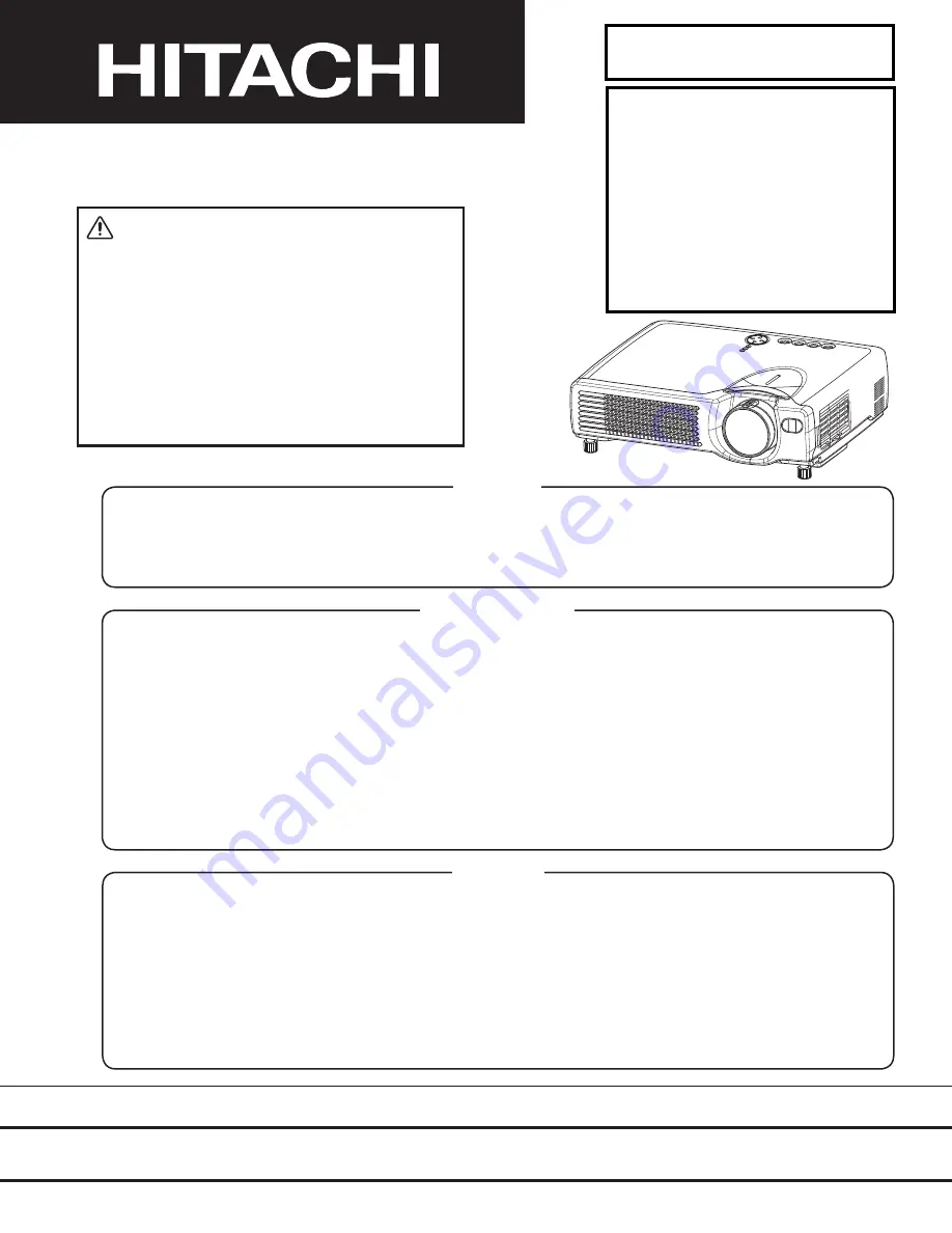
Multimedia LCD Projector
January 2003 Digital Media Division
SERVICE MANUAL
Be sure to read this manual before servicing. To assure safety from fire, electric shock, injury, harmful
radiation and materials, various measures are provided in this Hitachi Multimedia LCD Projector. Be sure
to read cautionary items described in the manual to maintain safety before servicing.
Caution
1. When replacing the lamp, avoid burns to your fingers. The lamp becomes very hot.
2. Never touch the lamp bulb with a finger or anything else. Never drop it or give it a shock. They may cause
bursting of the bulb.
3. This projector is provided with a high voltage circuit for the lamp. Do not touch the electric parts of power
unit (main), when turning on the projector.
4. Do not touch the exhaust fan, during operation.
5. The LCD module assembly is likely to be damaged. If replacing the LCD module assembly, do not hold
the FPC of the LCD module assembly.
6. Use the cables which are included with the projector or specified
Service Warning
1. Features --------------------------------------------------- 2
2. Specifi cations--------------------------------------------- 2
3. Names of each part ------------------------------------ 5
4. Adjustment ------------------------------------------------
7
5. Troubleshooting----------------------------------------
13
6. Service points ------------------------------------------
18
7. Block diagram ------------------------------------------
30
8. Connector connection diagram -------------------- 32
9. Wiring diagram -----------------------------------------
34
10.Basic circuit diagrams------------------------------- 40
11.Disassembly diagram --------------------------------- 59
12.Replacement parts list-------------------------------- 61
13.RS-232C communication ---------------------------- 64
Contents
:DUQLQJ
7KH WHFKQLFDO LQIRUPDWLRQ DQG SDUWV VKRZQ LQ WKLV
PDQXDO DUH QRW WR EH XVHG IRU WKH GHYHORSPHQW
GHVLJQSURGXFWLRQVWRUDJHRUXVHRIQXFOHDUFKHPLFDO
ELRORJLFDO RU PLVVLOH ZHDSRQV RU RWKHU ZHDSRQV RI
PDVVGHVWUXFWLRQRUPLOLWDU\SXUSRVHVRUSXUSRVHVWKDW
HQGDQJHU JOREDO VDIHW\ DQG SHDFH 0RUHRYHU GR QRW
VHOOJLYHRUH[SRUWWKHVHLWHPVRUJUDQWSHUPLVVLRQIRU
XVHWRSDUWLHVZLWKVXFKREMHFWLYHV)RUZDUGDOOLQTXLULHV
WR+LWDFKL/WG
CPS317(C3S3)
EDX3280AT(C3XM4ET)
Summary of Contents for C3S3
Page 34: ...33 Connector connection diagram C3S3E C3XM3E ...
Page 42: ...41 6 5 4 3 2 1 6 5 4 3 2 1 A B C D E F G POWER UNIT BALLAST C3S3 C3XM3 ...
Page 43: ...42 6 5 4 3 2 1 6 5 4 3 2 1 A B C D E F G POWER UNIT CIRCUIT C3S3 C3XM3 ...
Page 44: ...A B C D E F G 5 4 3 2 1 6 6 5 4 3 2 1 PWB assembly DRIVE 1 C3S3 C3XM3 43 1 ...
Page 45: ...A B C D E F G 5 4 3 2 1 6 6 5 4 3 2 1 PWB assembly DRIVE 2 C3S3 C3XM3 44 ...
Page 46: ...A B C D E F G 5 4 3 2 1 6 6 5 4 3 2 1 PWB assembly DRIVE 3 C3S3 C3XM3 45 ...
Page 47: ...A B C D E F G 5 4 3 2 1 6 6 5 4 3 2 1 PWB assembly DRIVE 4 C3S3 C3XM3 46 ...
Page 48: ...A B C D E F G 5 4 3 2 1 6 6 5 4 3 2 1 PWB assembly DRIVE 5 C3S3 C3XM3 47 ...
Page 49: ...A B C D E F G 5 4 3 2 1 6 6 5 4 3 2 1 PWB assembly DRIVE 6 C3S3 C3XM3 48 ...
Page 50: ...A B C D E F G 5 4 3 2 1 6 6 5 4 3 2 1 PWB assembly DRIVE 7 C3S3 C3XM3 49 ...
Page 51: ...A B C D E F G 5 4 3 2 1 6 6 5 4 3 2 1 PWB assembly DRIVE 8 C3S3 C3XM3 50 ...
Page 52: ...A B C D E F G 5 4 3 2 1 6 6 5 4 3 2 1 PWB assembly DRIVE 9 C3S3 C3XM3 51 ...
Page 53: ...A B C D E F G 5 4 3 2 1 6 6 5 4 3 2 1 PWB assembly DRIVE 10 C3S3 C3XM3 52 ...
Page 54: ...A B C D E F G 5 4 3 2 1 6 6 5 4 3 2 1 PWB assembly SIGNAL 1 C3S3 C3XM3 53 ...
Page 55: ...A B C D E F G 5 4 3 2 1 6 6 5 4 3 2 1 PWB assembly SIGNAL 2 C3S3 C3XM3 54 ...
Page 56: ...A B C D E F G 5 4 3 2 1 6 6 5 4 3 2 1 PWB assembly SIGNAL 3 C3S3 C3XM3 55 ...
Page 57: ...A B C D E F G 5 4 3 2 1 6 6 5 4 3 2 1 PWB assembly INPUT 1 C3S3E C3XM3E 56 ...
Page 58: ...A B C D E F G 5 4 3 2 1 6 6 5 4 3 2 1 PWB assembly INPUT 2 C3S3E C3XM3E 57 ...
Page 59: ...A B C D E F G 5 4 3 2 1 6 6 5 4 3 2 1 PWB assembly INPUT 3 C3S3E C3XM3E 58 ...
Page 62: ...THE UPDATED PARTS LIST FOR THIS MODEL IS AVAILABLE ON ESTA ...
Page 64: ...63 ...