9. Image menu
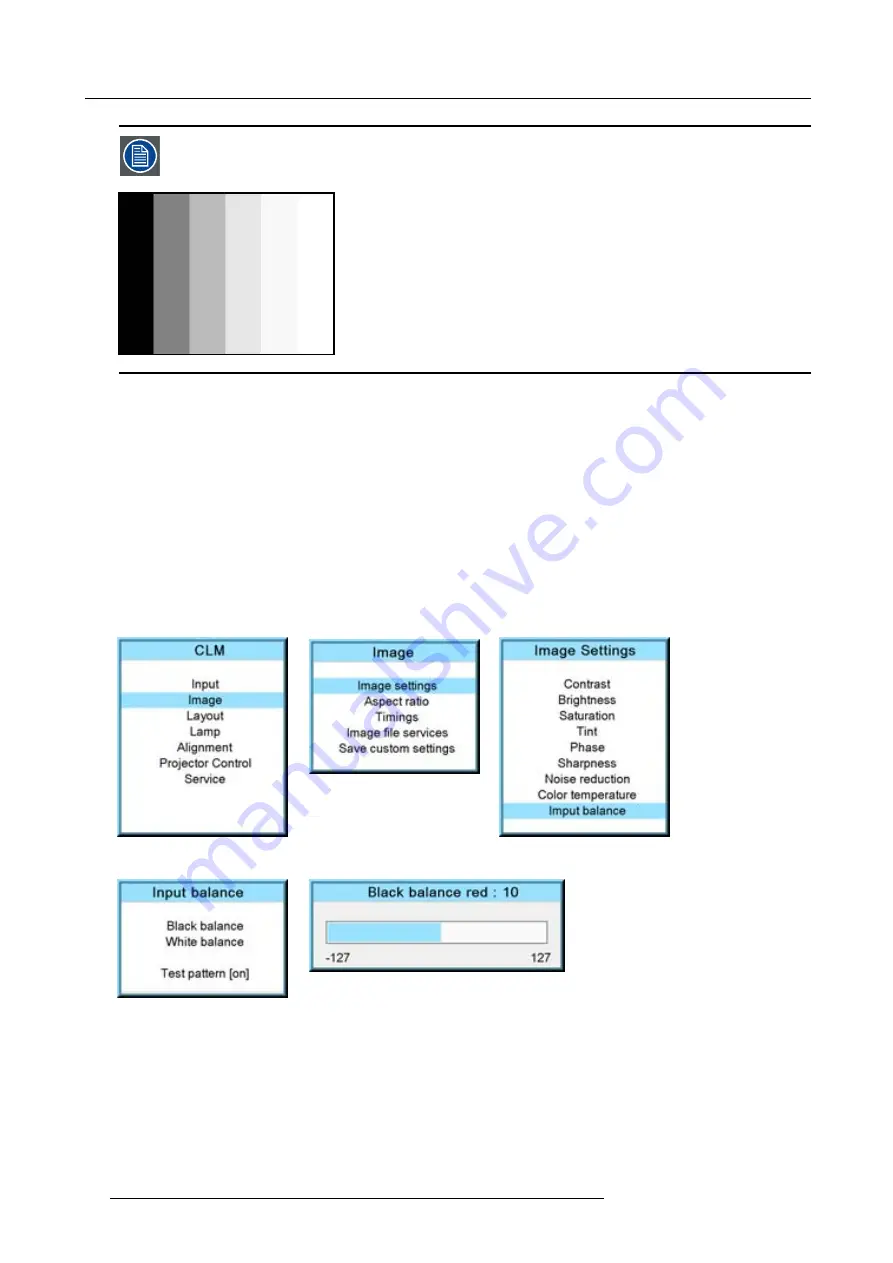
An alternative to a full screen White/black pattern is the standard gray scale pattern, the white bar will be used
for white balance and the black bar for black balance.
Image 9-45
Black balance
1. Press
MENU
to activate the menus.
2. Use the
▲
or
▼
key to select
Image
and press
ENTER
.
3. Use the
▲
or
▼
key to select
Image settings
and press
ENTER
.
4. Use the
▲
or
▼
key to select
Input balance
and press
ENTER
.
5. Do you want to use an internally generated test pattern ?
If yes, Use the
▲
or
▼
key to select
Test pattern
and press
ENTER
to toggle between [on] and [off]
If no, Adjust on the selected source.
6. Use the
▲
or
▼
key to select
Black balance
and press
ENTER
.
Depending whether a test pattern is selected or not, the adjustment image is displayed.
7. Toggle with
▲
or
▼
key to select
Black balance red
.
Image 9-46
Image 9-47
Image 9-48
Image 9-49
Image 9-50
8. Adjust the red black level on a minimal value
9. Toggle with
▲
or
▼
key to
Black balance blue
and adjust the blue black level on a minimal value.
Note:
This minimal value is not necessary , provided that the 2 other colors are not in
fl
uencing too much the color to be adjusted,
in fact the aim is to minimize the effect of the two other colors since there is a risk of reaching too soon the 50% transition
due to the contribution of these two other colors signals.
10.Toggle with
▲
or
▼
key to
Black balance green
and adjust the Green black level until bright spots appear on the screen.
11.Toggle with
▲
or
▼
key to
Black balance blue
adjust the Blue black level until bright spots appear on the screen.
12.Toggle with
▲
or
▼
key to
Black balance red
adjust the Red black level until bright spots appear on the screen.
82
R59770021 CLM R10+ 15/03/2010
Summary of Contents for R9050100
Page 1: ...CLM R10 Users manual R9050100 R90501001 R59770021 10 15 03 2010...
Page 14: ...1 Safety 10 R59770021 CLM R10 15 03 2010...
Page 22: ...2 General 18 R59770021 CLM R10 15 03 2010...
Page 35: ...3 Physical installation Skew Image 3 28 Skew adjustment R59770021 CLM R10 15 03 2010 31...
Page 36: ...3 Physical installation 32 R59770021 CLM R10 15 03 2010...
Page 48: ...5 Connections 44 R59770021 CLM R10 15 03 2010...
Page 64: ...7 Start up of the Adjustment mode 60 R59770021 CLM R10 15 03 2010...
Page 74: ...8 Input menu 70 R59770021 CLM R10 15 03 2010...
Page 116: ...10 Layout menu 112 R59770021 CLM R10 15 03 2010...
Page 158: ...13 Projector control 154 R59770021 CLM R10 15 03 2010...
Page 172: ...14 Service menu 168 R59770021 CLM R10 15 03 2010...
Page 186: ...16 Servicing 182 R59770021 CLM R10 15 03 2010...
Page 196: ...17 Projector covers removal and installation 192 R59770021 CLM R10 15 03 2010...
Page 204: ...C DMX Chart 200 R59770021 CLM R10 15 03 2010...
Page 210: ...D Specifications 206 R59770021 CLM R10 15 03 2010...
Page 216: ...E Troubleshooting 212 R59770021 CLM R10 15 03 2010...
Page 222: ...F Mounting optional Carry handle 218 R59770021 CLM R10 15 03 2010...
Page 224: ...G Order info 220 R59770021 CLM R10 15 03 2010...


