14. Service menu
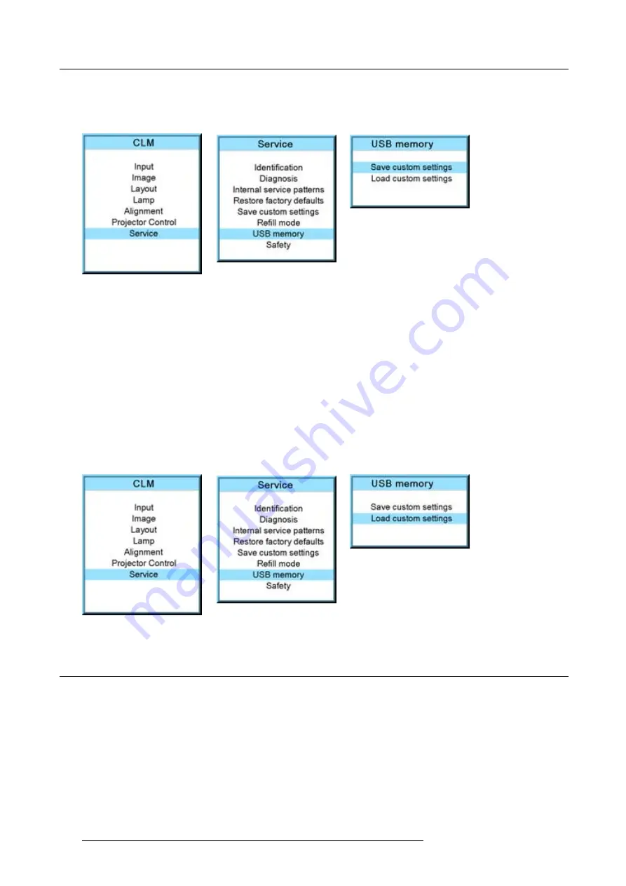
The custom settings on the projector are stored on the USB device together with the serial number of the projector. Different
saves can be made from different projectors on the same USB device.
When there is no USB device connected to the USB slot, a message,
No USB device found
, is displayed.
Image 14-49
Image 14-50
Image 14-51
Load custom settings
1. Connect a FAT 16 formatted USB device to the USB port.
2. Press
MENU
to activate the menus.
3. Use the
▲
or
▼
key to select
Service
and press
ENTER
.
The service window opens.
4. Use the
▲
or
▼
key to select
USB memory
and press
ENTER
.
5. Use the
▲
or
▼
key to select
Load custom settings
and press
ENTER
.
An list of serial numbers is given.
6. Use the
▲
or
▼
key to select the serial number to start from to load the settings.
The settings from the selected projector on the USB device are loaded into the current attached projector. The current projector
settings are overwritten with these settings.
Image 14-52
Image 14-53
Image 14-54
14.9 Over temperature DMD safety
What can be done
When the temperature of the DMD becomes higher than the normal operation temperature (between 60 and 64 °C) it is possible to
switch the lamp mode of the projector automatically from 4 lamps to 2 lamps so that the DMD temperature can cool down. A warning
remains on the local LCD panel and the warning LED is on as long as the temperature is too high. When the temperature exceeds
64°C then the projector is switched to standby and an error is displayed on the LCD panel.
How to con
fi
gure the over temperature safety
1. Press
MENU
to activate the menus.
2. Use the
▲
or
▼
key to select
Service
and press
ENTER
.
3. Use the
▲
or
▼
key to select
Safety
and press
ENTER
.
166
R59770021 CLM R10+ 15/03/2010
Summary of Contents for R9050100
Page 1: ...CLM R10 Users manual R9050100 R90501001 R59770021 10 15 03 2010...
Page 14: ...1 Safety 10 R59770021 CLM R10 15 03 2010...
Page 22: ...2 General 18 R59770021 CLM R10 15 03 2010...
Page 35: ...3 Physical installation Skew Image 3 28 Skew adjustment R59770021 CLM R10 15 03 2010 31...
Page 36: ...3 Physical installation 32 R59770021 CLM R10 15 03 2010...
Page 48: ...5 Connections 44 R59770021 CLM R10 15 03 2010...
Page 64: ...7 Start up of the Adjustment mode 60 R59770021 CLM R10 15 03 2010...
Page 74: ...8 Input menu 70 R59770021 CLM R10 15 03 2010...
Page 116: ...10 Layout menu 112 R59770021 CLM R10 15 03 2010...
Page 158: ...13 Projector control 154 R59770021 CLM R10 15 03 2010...
Page 172: ...14 Service menu 168 R59770021 CLM R10 15 03 2010...
Page 186: ...16 Servicing 182 R59770021 CLM R10 15 03 2010...
Page 196: ...17 Projector covers removal and installation 192 R59770021 CLM R10 15 03 2010...
Page 204: ...C DMX Chart 200 R59770021 CLM R10 15 03 2010...
Page 210: ...D Specifications 206 R59770021 CLM R10 15 03 2010...
Page 216: ...E Troubleshooting 212 R59770021 CLM R10 15 03 2010...
Page 222: ...F Mounting optional Carry handle 218 R59770021 CLM R10 15 03 2010...
Page 224: ...G Order info 220 R59770021 CLM R10 15 03 2010...


