


23 / 34
0006081545_201305
ESP
AÑOL
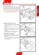
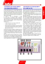
su valor de regulación hasta verificar su activación al que tiene
que seguir la parada inmediata en “bloqueo” del quemador.
Desbloquee el quemador pulsando el botón correspondiente (8)
y regule el control de la presión a un valor que sea suficiente
para detectar la presión del aire existente durante la fase de
preventilación de la primera etapa.
• El presostato de control de presión de gas (mínima) tiene como
fin impedir el funcionamiento del quemador cuando la presión
de gas no es la prevista. El presostato de mínima debe usar el
contacto que está cerrado cuando el presostato detecta una
presión superior a la que ha sido regulado. La regulación del
presostato de mínima tiene que realizarse cuando se pone en
funcionamiento el quemador en función de la presión que se
detecta vez por vez. La intervención (apertura del circuito) de
cualquiera de los presostatos cuando el quemador está funcio-
nando (llama encendida) determina inmediatamente la parada
del quemador. Con el primer encendido del quemador, es in-
dispensable verificar el funcionamiento correcto del presostato.
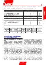
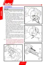
Una vez terminadas las regulaciones, comprobar visualmente
que la lámina en la que funciona el cojinete, tenga un perfil
progresivo. Comprobar, además, con los instrumentos
correspondientes que durante los pasajes de la primera a
la segunda etapa, los parámetros de combustión no sean
muy diferentes de los valores optimales.
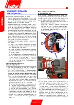
fotocÉlUlA Uv
Una leve untuosidad compromete fuertemente el pasaje de los
rayos ultravioletas a través del bulbo de la fotocélula UV impidiendo
que el elemento sensible interno reciba la cantidad de radiaciones
necesarias para un correcto funcionamiento. Si la cubeta de cristal
está sucia de gasóleo, petróleo pesado, etc., es indispensable
limpiarla adecuadamente.
Aún el simple contacto con los dedos puede dejar una
leve untuosidad que será suficiente para comprometer el
funcionamiento de la fotocélula UV.
La fotocélula UV no detecta la luz del día o la de una lámpara común.
La eventual verificación de la sensibilidad se puede efectuar con
la llama de un encendedor, con una vela, o bien con la descarga
eléctrica que se manifiesta entre los electrodos de un común
transformador de encendido.
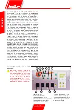
Para asegurar un funcionamiento correcto, el valor de la corriente
de la célula UV debe ser suficientemente estable y no descender
por debajo del valor mínimo requerido por el equipo específico.
Este valor está escrito también en el esquema eléctrico. Puede
ser necesario buscar en modo experimental la mejor posición
haciendo deslizar (con un movimiento axial o de rotación) el
cuerpo que contiene la fotocélula respecto a la banda de fijación.
La verificación se efectúa introduciendo un microamperímetro, con
escala adecuada, en serie a uno de los dos cables de conexión de
la fotocélula UV; obviamente hay que respetar la polaridad (+ y -).
el equipo LME 73... necesita una corriente de célula comprendida
entre 200 y 500 microA.
controles
• Una vez encendido el quemador es necesario controlar los
dispositivos de seguridad (detector de llama, de bloqueo,
termostatos).
• El dispositivo de control de la llama, debe ser capaz de intervenir
durante el funcionamiento, en el caso de que la llama se apague
(este control debe ser efectuado pasado al menos 1 minuto
desde que se haya producido el encendido).
• El quemador debe estar en condiciones de bloquearse y
permanecer en esta posición si durante la fase de encendi-
do y durante el tiempo establecido por la caja de control no
aparece una llama de forma normal. El bloqueo conlleva la
parada inmediata del motor y, por consiguiente, la parada del
quemador, y se iluminará la señal correspondiente de bloqueo.
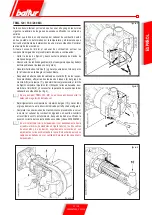
Para controlar la eficiencia de la fotocélula UV y del bloqueo,
siga las instrucciones siguientes:
- Ponga el quemador en funcionamiento.
- Pasado al menos un minuto del encendido extraer el detector
de la llama sacándolo de su alojamiento, oscurecerlo simu-
lando así la falta de llama. (cerrar con un trapo la apertura
del detector de la llama. De este modo se apaga la llama
del quemador. El equipo, en el tiempo determinado por el
programa, se bloquea. Desbloquear el aparato sólo con la
intervención manual presionado el pulsador correspondiente.
• 3) Para controlar la eficiencia de los termostatos, se pone en
marcha el quemador hasta cuando el agua en la caldera alcanza
una temperatura de por lo menos 50° C, y luego se actúa en el
tirador de mando del termostato para bajar la temperatura hasta
oír un clic de apertura y al mismo tiempo la parada del quemador.
El clic del termostato debe ocurrir con una diferencia máxima
de 5 + 10° C con respecto al termostato de control (termómetro
de caldera); de lo contrario modificar la calibración de la escala
del termostato, haciéndola corresponder a la del termómetro.
Summary of Contents for TBML 80 MC
Page 2: ......
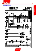
Page 33: ...31 34 0006081545_201305 ENGLISH WIRING DIAGRAM...
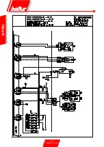
Page 34: ...32 34 0006081545_201305 ENGLISH...
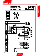
Page 35: ...33 34 0006081545_201305 ENGLISH...
Page 67: ...31 34 0006081545_201305 ESPA OL ESQUEMA EL CTRICO...
Page 68: ...32 34 0006081545_201305 ESPA OL...
Page 69: ...33 34 0006081545_201305 ESPA OL...
Page 101: ...31 34 0006081545_201305 ITALIANO T RK E DEUTSCH SCHALTPLAN...
Page 102: ...32 34 0006081545_201305 ITALIANO T RK E DEUTSCH...
Page 103: ...33 34 0006081545_201305 ITALIANO T RK E DEUTSCH...
Page 135: ...31 34 0006081545_201305 T RK E ELEKTR K EMASI...
Page 136: ...32 34 0006081545_201305 T RK E...
Page 137: ...33 34 0006081545_201305 T RK E...
Page 140: ...2 34 0006081545_201305 5 8 SUNTEC 14 15 LME 73 16 17 19 19 21 21 22 24 25 26 28 31...
Page 141: ...3 34 0006081545_201305 BALTUR...
Page 142: ...4 34 0006081545_201305 3 2 RC B...
Page 146: ...8 34 0006081545_201305 5 6 0002934670 3 2 4 1 7...
Page 147: ...9 34 0006081545_201305 10 11 12 000293640 65 80...
Page 148: ...0002911090 10 34 0006081545_201305 EN 676 1 2 3 4 5 6 7 1200 8 9 10 11 12 13...
Page 154: ...16 34 0006081545_201305 LME 73 1 EK EK 2 1 2 BCI AZL2 1 TW...
Page 157: ...19 34 0006081545_201305 O K1 9 2800 9 1 2 1 2 1 1 1 000293 1 1 1 2 2 2...
Page 158: ...13 12 acc_reg001 psd TBML 80MC 003 psd 20 34 0006081545_201305 2 13 2 2 CO2 10 13 2...
Page 159: ...1 7 8 2 3 4 5 6 10 9 Display TBML 80 PN GAS L 21 34 0006081545_201305 1 2 3 4 5 3 7 8...
Page 161: ...23 34 0006081545_201305 1 8 1 1 2 LME 73 200 500 1 3 50 C 5 10 C...
Page 164: ...26 34 0006081545_201305 TBML 80 MC 1 2 3 4 5 6 7 8 9 10 4 0002936380...
Page 169: ...31 34 0006081545_201305...
Page 170: ...32 34 0006081545_201305...
Page 171: ...33 34 0006081545_201305...
Page 174: ...2 34 0006081545_201305 5 8 10 11 SUNTEC 14 15 LME 73 16 17 19 19 21 21 22 24 25 26 28 31...
Page 175: ...3 34 0006081545_201305 a b c a b c d e f g...
Page 176: ...4 34 0006081545_201305 3mm 2 RC a b c d e a b a b c d...
Page 180: ...8 34 0006081545_201305 6 5 0002934670 3 2 7 4 1...
Page 181: ...9 34 0006081545_201305 M 10 11 4 12 0002936400 DN65 DN80...
Page 182: ...0002911090 10 34 0006081545_201305 E N 6 7 6 1 2 3 4 5 6 7 1200 kW 8 9 10 11 12 13...
Page 188: ...16 34 0006081545_201305 LME 73 1 EK LED EK LED 1 2 BCI AZL2 1 LED TW...
Page 191: ...19 34 0006081545_201305 O K1 9 1 2 2800 rpm 9 000293 13 CO2 10 13...
Page 192: ...13 12 acc_reg001 psd TBML 80MC 003 psd 20 34 0006081545_201305...
Page 193: ...1 7 8 2 3 4 5 6 10 9 Display TBML 80 PN GAS L 21 34 0006081545_201305 1 2 3 L E D 3 4 5 3 7 8...
Page 195: ...23 34 0006081545_201305 UV UV UV UV UV UV LME 73 200 500 1 1 50 C 5 10 C...
Page 198: ...26 34 0006081545_201305 TBML 80 MC 1 2 3 4 5 6 7 8 9 10 4 0002936380...
Page 199: ...27 34 0006081545_201305 TBML 120 160 200 MC 1 2 3 4 5 6 7 8 9 3 TBML 200 MC 10 4 0002936380...
Page 203: ...31 34 0006081545_201305...
Page 204: ...32 34 0006081545_201305...
Page 205: ...33 34 0006081545_201305...
Page 207: ......


