


4 / 34
0006081545_201305
ENGLISH
ELECTRICAL SUPPLY
• The equipment is electrically safe only when it is correctly connected to an
effi cient ground connection carried out in accordance with current safety
regulations. It is necessary to check this essential safety requirement.
If in doubt, call for a careful electrical check by a qualifi ed technicians,
since the manufacturer will not be liable for any damage caused by a
poor ground connection.
• Have qualifi ed technicians check that the wiring is suitable for the
maximum power absorption of the equipment, as indicated in the technical
plate, making sure in particular that the diameter of cables is suffi cient
for the equipment’s power absorption.
• Adapters, multiple plugs and extension cables may not be used for the
equipment’s power supply.
• According to current safety regulations, an omnipolar switch with a contact
opening gap of at least 3 mm is required for the mains supply connection.
• Extract the power cable external insulation as strictly necessary for the
connection, in order to avoid that the cable comes into contact with metal
parts.
• An ominpolar switch in accordance with current safety regulations is
required for the mains supply connection.
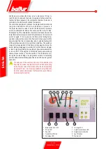
• The electrical supply to the burner must have neutral to ground
connection. If the ionisation current has control with neutral not to ground
it is essential to make a connection between terminal 2 (neutral) and the
ground for the RC circuit.
• The use of any components that use electricity means that certain
fundamental rules have to followed, including the following:
- do not touch the equipment with parts of the body that are wet or damp
or with damp feet
- do not pull on electrical cables
- do not leave the equipment exposed to atmospheric agents (such as
rain or sun etc.) unless there is express provision for this.
- do not allow the equipment to be used by children or inexpert
persons.
• The power supply cable for the equipment not must be replaced by the
user. If the cable gets damaged, switch off the equipment, and call only
on qualifi ed technicians for its replacement.
• If you decide not to use the equipment for a while it is advisable to switch
off the electrical power supply to all components in the system that use
electricity (pumps, burner, etc.).
GAS, LIGHT OIL, OR OTHER FUEL SUPPLIES
General warning notes
• Installation of the burner must be carried out by qualifi ed technicians
and in compliance with current law and regulations, since incorrect
installation may cause damage to person, animals or things, for which
damage the manufacturer shall not can be held responsible.
• Before installation it is advisable to carry out careful internal cleaning
of all tubing for the fuel feed system to remove any residues that could
jeopardise the proper working of the burner.
• For fi rst start up of the equipment have qualifi ed technicians carry out
the following checks:
• If you decide not to use the burner for a while, close the tap or taps that
supply the fuel.
Special warning notes when using gas
• Have qualifi ed technicians check the following:
a) that the feed line and the train comply with current law and
regulations.
b) that all the gas connections are properly sealed.
• Do not use the gas pipes to ground electrical equipment.
• Do not leave the equipment on when it is not in use and always close
the gas tap.
• If the user of is away for some time, close the main gas feed tap to the
burner.
• If you smell gas:
a) do not use any electrical switches, the telephone or any other object
that could produce a spark;
b) immediately open doors and windows to create a current of air that
will purify the room;
c) close the gas taps;
d) ask for the help of qualifi ed technicians.
• Do not block ventilation openings in the room where there is gas
equipment or dangerous situations may arise with the build up of toxic
and explosive mixtures.
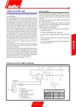
FLUES FOR HIGH EFFICIENCY BOILERS AND SIMILAR
It should be pointed out that high effi ciency boilers and similar discharge
combustion products (fumes) at relatively low temperatures into the fl ue.
In the above situation, traditional fl ues (in terms of their diameter and heat
insulation) may be suitable because the signifi cant cooling of the combustion
products in these permits temperatures to fall even below the condensation
point. In a fl ue that works with condensation there is soot at the point the
exhaust reaches the atmosphere when burning light oil or heavy oil or the
presence of condensate water along the fl ue itself when gas is being burnt
(methane, LPG, etc.). Flues connected to high effi ciency boilers and similar
must therefore be of a size (section and heat insulation) for the specifi c use
to avoid such problems as those described above.
WARNING NOTES FOR THE USER HOW TO USE THE BURNER SAFELY
Summary of Contents for TBML 80 MC
Page 2: ......
Page 33: ...31 34 0006081545_201305 ENGLISH WIRING DIAGRAM...
Page 34: ...32 34 0006081545_201305 ENGLISH...
Page 35: ...33 34 0006081545_201305 ENGLISH...
Page 67: ...31 34 0006081545_201305 ESPA OL ESQUEMA EL CTRICO...
Page 68: ...32 34 0006081545_201305 ESPA OL...
Page 69: ...33 34 0006081545_201305 ESPA OL...
Page 101: ...31 34 0006081545_201305 ITALIANO T RK E DEUTSCH SCHALTPLAN...
Page 102: ...32 34 0006081545_201305 ITALIANO T RK E DEUTSCH...
Page 103: ...33 34 0006081545_201305 ITALIANO T RK E DEUTSCH...
Page 135: ...31 34 0006081545_201305 T RK E ELEKTR K EMASI...
Page 136: ...32 34 0006081545_201305 T RK E...
Page 137: ...33 34 0006081545_201305 T RK E...
Page 140: ...2 34 0006081545_201305 5 8 SUNTEC 14 15 LME 73 16 17 19 19 21 21 22 24 25 26 28 31...
Page 141: ...3 34 0006081545_201305 BALTUR...
Page 142: ...4 34 0006081545_201305 3 2 RC B...
Page 146: ...8 34 0006081545_201305 5 6 0002934670 3 2 4 1 7...
Page 147: ...9 34 0006081545_201305 10 11 12 000293640 65 80...
Page 148: ...0002911090 10 34 0006081545_201305 EN 676 1 2 3 4 5 6 7 1200 8 9 10 11 12 13...
Page 154: ...16 34 0006081545_201305 LME 73 1 EK EK 2 1 2 BCI AZL2 1 TW...
Page 157: ...19 34 0006081545_201305 O K1 9 2800 9 1 2 1 2 1 1 1 000293 1 1 1 2 2 2...
Page 158: ...13 12 acc_reg001 psd TBML 80MC 003 psd 20 34 0006081545_201305 2 13 2 2 CO2 10 13 2...
Page 159: ...1 7 8 2 3 4 5 6 10 9 Display TBML 80 PN GAS L 21 34 0006081545_201305 1 2 3 4 5 3 7 8...
Page 161: ...23 34 0006081545_201305 1 8 1 1 2 LME 73 200 500 1 3 50 C 5 10 C...
Page 164: ...26 34 0006081545_201305 TBML 80 MC 1 2 3 4 5 6 7 8 9 10 4 0002936380...
Page 169: ...31 34 0006081545_201305...
Page 170: ...32 34 0006081545_201305...
Page 171: ...33 34 0006081545_201305...
Page 174: ...2 34 0006081545_201305 5 8 10 11 SUNTEC 14 15 LME 73 16 17 19 19 21 21 22 24 25 26 28 31...
Page 175: ...3 34 0006081545_201305 a b c a b c d e f g...
Page 176: ...4 34 0006081545_201305 3mm 2 RC a b c d e a b a b c d...
Page 180: ...8 34 0006081545_201305 6 5 0002934670 3 2 7 4 1...
Page 181: ...9 34 0006081545_201305 M 10 11 4 12 0002936400 DN65 DN80...
Page 182: ...0002911090 10 34 0006081545_201305 E N 6 7 6 1 2 3 4 5 6 7 1200 kW 8 9 10 11 12 13...
Page 188: ...16 34 0006081545_201305 LME 73 1 EK LED EK LED 1 2 BCI AZL2 1 LED TW...
Page 191: ...19 34 0006081545_201305 O K1 9 1 2 2800 rpm 9 000293 13 CO2 10 13...
Page 192: ...13 12 acc_reg001 psd TBML 80MC 003 psd 20 34 0006081545_201305...
Page 193: ...1 7 8 2 3 4 5 6 10 9 Display TBML 80 PN GAS L 21 34 0006081545_201305 1 2 3 L E D 3 4 5 3 7 8...
Page 195: ...23 34 0006081545_201305 UV UV UV UV UV UV LME 73 200 500 1 1 50 C 5 10 C...
Page 198: ...26 34 0006081545_201305 TBML 80 MC 1 2 3 4 5 6 7 8 9 10 4 0002936380...
Page 199: ...27 34 0006081545_201305 TBML 120 160 200 MC 1 2 3 4 5 6 7 8 9 3 TBML 200 MC 10 4 0002936380...
Page 203: ...31 34 0006081545_201305...
Page 204: ...32 34 0006081545_201305...
Page 205: ...33 34 0006081545_201305...
Page 207: ......


