


24 / 34
0006081545_201305
ENGLISH
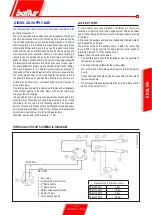
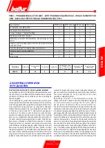
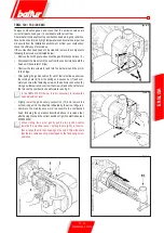
X= Head-disc distance; adjust distance X following the below
instructions:
• loosen screw 1
• turn screw 2 to position the combustion head 3, referring to
index 4.
adjust distance X between the minimum and maximum value
according to what is indicated in the table..
TBML 80 MC ÷ 160MC HEAD REGULATION DIAGRAM
AIR REGULATION ON THE
COMBUSTION HEAD
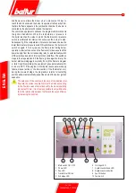
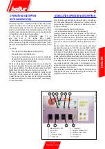
The combustion head has an adjustment device so that the air
passage between the disk and the combustion head is opened
or closed. You are thus able to obtain, closing the passage, high
pressure upstream of the disk even at low capacity. The high speed
and turbulence of the air provides for its greater penetration into the
fuel and therefore an excellent mixture and flame stability. It can
be indispensable to have high air pressure upstream of the disc to
prevent flame pulsations. This condition is practically indispensable
when the burner works with a furnace that is pressurized and/or has
a high heat load.
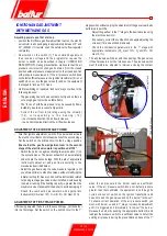
It is clear from the above that the device that closes the air to the
combustion head must be set at a position such as to
always
obtain
very high air pressure behind the disk It is advisable to adjust it in
such a way as to obtain a closure of the air at the combustion head
that will require a significant opening of the air shutter that regulates
the aspiration flow from the burner fan. It is recommended to provide
an air closure on the head that requires a noticeable opening of
the air lock that regulates the burner fan intake flow. Obviously this
condition must occur when the burner operates at the maximum
required output. In practice, start by adjusting the device that closes
the air on the combustion head to an intermediate position, turning
on the burner for a preliminary adjustment as described above.
When the
required maximum supply
has been reached,
the position of the device that closes the air at the
combustion head has to be corrected, moving it forward
and backwards, in order to obtain an air flow suitable for
the supply
with the air shutter considerably open.
X
Value indicated by index 4
TBML 80 MC
87 ÷ 95
1 ÷ 1.5
TBML 120 MC
119 ÷ 155
1 ÷ 5
TBML 160 MC
119 ÷ 155
1 ÷ 5
The above presented adjustments are approximate; position
the combustion head in function of the furnace specifications.
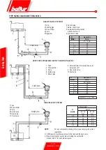
X= Head-disc distance; adjust distance X following the below
instructions:
• loosen screw 1
• turn screw 2 to position the combustion head 3 in reference to
index 4.
• adjust distance X between the minimum and maximum value
according to what is indicated in the table.
X
Value indicated by index 4
TBML 200 MC
110 ÷ 150
4 ÷ 1
Summary of Contents for TBML 80 MC
Page 2: ......
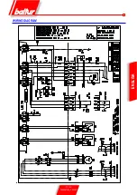
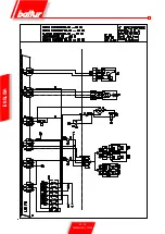
Page 33: ...31 34 0006081545_201305 ENGLISH WIRING DIAGRAM...
Page 34: ...32 34 0006081545_201305 ENGLISH...
Page 35: ...33 34 0006081545_201305 ENGLISH...
Page 67: ...31 34 0006081545_201305 ESPA OL ESQUEMA EL CTRICO...
Page 68: ...32 34 0006081545_201305 ESPA OL...
Page 69: ...33 34 0006081545_201305 ESPA OL...
Page 101: ...31 34 0006081545_201305 ITALIANO T RK E DEUTSCH SCHALTPLAN...
Page 102: ...32 34 0006081545_201305 ITALIANO T RK E DEUTSCH...
Page 103: ...33 34 0006081545_201305 ITALIANO T RK E DEUTSCH...
Page 135: ...31 34 0006081545_201305 T RK E ELEKTR K EMASI...
Page 136: ...32 34 0006081545_201305 T RK E...
Page 137: ...33 34 0006081545_201305 T RK E...
Page 140: ...2 34 0006081545_201305 5 8 SUNTEC 14 15 LME 73 16 17 19 19 21 21 22 24 25 26 28 31...
Page 141: ...3 34 0006081545_201305 BALTUR...
Page 142: ...4 34 0006081545_201305 3 2 RC B...
Page 146: ...8 34 0006081545_201305 5 6 0002934670 3 2 4 1 7...
Page 147: ...9 34 0006081545_201305 10 11 12 000293640 65 80...
Page 148: ...0002911090 10 34 0006081545_201305 EN 676 1 2 3 4 5 6 7 1200 8 9 10 11 12 13...
Page 154: ...16 34 0006081545_201305 LME 73 1 EK EK 2 1 2 BCI AZL2 1 TW...
Page 157: ...19 34 0006081545_201305 O K1 9 2800 9 1 2 1 2 1 1 1 000293 1 1 1 2 2 2...
Page 158: ...13 12 acc_reg001 psd TBML 80MC 003 psd 20 34 0006081545_201305 2 13 2 2 CO2 10 13 2...
Page 159: ...1 7 8 2 3 4 5 6 10 9 Display TBML 80 PN GAS L 21 34 0006081545_201305 1 2 3 4 5 3 7 8...
Page 161: ...23 34 0006081545_201305 1 8 1 1 2 LME 73 200 500 1 3 50 C 5 10 C...
Page 164: ...26 34 0006081545_201305 TBML 80 MC 1 2 3 4 5 6 7 8 9 10 4 0002936380...
Page 169: ...31 34 0006081545_201305...
Page 170: ...32 34 0006081545_201305...
Page 171: ...33 34 0006081545_201305...
Page 174: ...2 34 0006081545_201305 5 8 10 11 SUNTEC 14 15 LME 73 16 17 19 19 21 21 22 24 25 26 28 31...
Page 175: ...3 34 0006081545_201305 a b c a b c d e f g...
Page 176: ...4 34 0006081545_201305 3mm 2 RC a b c d e a b a b c d...
Page 180: ...8 34 0006081545_201305 6 5 0002934670 3 2 7 4 1...
Page 181: ...9 34 0006081545_201305 M 10 11 4 12 0002936400 DN65 DN80...
Page 182: ...0002911090 10 34 0006081545_201305 E N 6 7 6 1 2 3 4 5 6 7 1200 kW 8 9 10 11 12 13...
Page 188: ...16 34 0006081545_201305 LME 73 1 EK LED EK LED 1 2 BCI AZL2 1 LED TW...
Page 191: ...19 34 0006081545_201305 O K1 9 1 2 2800 rpm 9 000293 13 CO2 10 13...
Page 192: ...13 12 acc_reg001 psd TBML 80MC 003 psd 20 34 0006081545_201305...
Page 193: ...1 7 8 2 3 4 5 6 10 9 Display TBML 80 PN GAS L 21 34 0006081545_201305 1 2 3 L E D 3 4 5 3 7 8...
Page 195: ...23 34 0006081545_201305 UV UV UV UV UV UV LME 73 200 500 1 1 50 C 5 10 C...
Page 198: ...26 34 0006081545_201305 TBML 80 MC 1 2 3 4 5 6 7 8 9 10 4 0002936380...
Page 199: ...27 34 0006081545_201305 TBML 120 160 200 MC 1 2 3 4 5 6 7 8 9 3 TBML 200 MC 10 4 0002936380...
Page 203: ...31 34 0006081545_201305...
Page 204: ...32 34 0006081545_201305...
Page 205: ...33 34 0006081545_201305...
Page 207: ......


