23 / 34
0006081545_201305
ENGLISH
stage.
• The gas control pressure switch (minimum) prevents burner
operation when gas pressure is not the foreseen one. The
minimum pressure switch must make use of the contact which
is closed when the pressure switch detects a pressure higher
than its own setting. Therefore the adjustment of the minimum
pressure switch must be carried out when the burner is started
up, in accordance with the pressure that is found from time to
time. The triggering (opening of the circuit) of any of the pressure
switches when the burner is running (flame on) causes the
burner to stop immediately. When first switching on the burner
it is essential to check that it works properly.
Once the adjusting operations are completed, visually check
that the thin plate on which the bearing acts has a progressive
profile. Using the special instruments check also that in the
passage from the 1
st
to the 2
nd
stage combustion parameters
do not move too much away from the optimal values.
UV PHOTOCELL
Even the slightest greasiness will compromise the passage of the
ultraviolet rays through the UV photocell bulb, thus preventing the
sensitive internal element from receiving the quantity of radiation
necessary for it to work properly. If the bulb is fouled with diesel fuel,
fuel oil, etc., it must be properly cleaned.
Even by simply touching the bulb with fingers, it is possible
to leave a slight greasiness which could compromise UV
photocell operation.
The UV cell does not detect daylight or the light from a common
lamp. Sensitivity can be checked with a flame (cigarette lighter,
candle) or with the electric discharge between the electrodes of a
common ignition transformer.
To ensure proper operation, the UV cell current value should be
sufficiently stable and should not drop below the minimum value
required by the specific equipment; this value is indicated in the
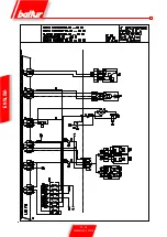
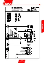
wiring diagram. It may be necessary to search for the best position
by sliding (axial or rotational movement) the casing that contains the
photocell with respect to the fastening clamp. This can be checked
by connecting a micro-ammeter, with a suitable scale, in series to
one of the two UV photocell connection cables. Obviously the polarity
(+ and -) must be respected.
LME 73... equipment needs a cell current between 200 and 500
microA.
CHECKS
• After starting up the burner, check the safety devices (flame
detector, lock-out system, thermostats).
• The flame control device should trip if the flame extinguishes
during operation (this check should be made after at least 1
minute after ignition).
• The burner should be capable of blocking itself and remain
so when a normal flame does not come on during start-up
cycle and within the pre-set on control box. The lock-out
causes the immediate stop of the motor and burner and the
switching on of the corresponding lock-out light indication.
To check the efficiency of the flame detector and lock-out system,
proceed as follows:
- Start the burner.
- After at least one minute, remove the flame detector from its
housing and simulate flame failure. (use a rag to close the
specific opening on the flame detector). The burner flame
should go to out. The burner goes into lock-out within the
time pre-set by the program. The equipment can be reset
only manually by pressing the specific button.
• 3) To check thermostat efficiency, make the burner work
until the water inside the boiler reaches a temperature
of at least 50°C. Then, use the thermostat control
knob to reduce the temperature until you perceive an
opening click and the burner stopping at the same time.
The thermostat tripping should occur with a deviation of 5 ÷ 10
°C with respect to the control thermometer (boiler thermometer).
Alternatively, change the setting of the thermostat scale making
it correspond to that of the thermometer.
Summary of Contents for TBML 80 MC
Page 2: ......
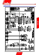
Page 33: ...31 34 0006081545_201305 ENGLISH WIRING DIAGRAM...
Page 34: ...32 34 0006081545_201305 ENGLISH...
Page 35: ...33 34 0006081545_201305 ENGLISH...
Page 67: ...31 34 0006081545_201305 ESPA OL ESQUEMA EL CTRICO...
Page 68: ...32 34 0006081545_201305 ESPA OL...
Page 69: ...33 34 0006081545_201305 ESPA OL...
Page 101: ...31 34 0006081545_201305 ITALIANO T RK E DEUTSCH SCHALTPLAN...
Page 102: ...32 34 0006081545_201305 ITALIANO T RK E DEUTSCH...
Page 103: ...33 34 0006081545_201305 ITALIANO T RK E DEUTSCH...
Page 135: ...31 34 0006081545_201305 T RK E ELEKTR K EMASI...
Page 136: ...32 34 0006081545_201305 T RK E...
Page 137: ...33 34 0006081545_201305 T RK E...
Page 140: ...2 34 0006081545_201305 5 8 SUNTEC 14 15 LME 73 16 17 19 19 21 21 22 24 25 26 28 31...
Page 141: ...3 34 0006081545_201305 BALTUR...
Page 142: ...4 34 0006081545_201305 3 2 RC B...
Page 146: ...8 34 0006081545_201305 5 6 0002934670 3 2 4 1 7...
Page 147: ...9 34 0006081545_201305 10 11 12 000293640 65 80...
Page 148: ...0002911090 10 34 0006081545_201305 EN 676 1 2 3 4 5 6 7 1200 8 9 10 11 12 13...
Page 154: ...16 34 0006081545_201305 LME 73 1 EK EK 2 1 2 BCI AZL2 1 TW...
Page 157: ...19 34 0006081545_201305 O K1 9 2800 9 1 2 1 2 1 1 1 000293 1 1 1 2 2 2...
Page 158: ...13 12 acc_reg001 psd TBML 80MC 003 psd 20 34 0006081545_201305 2 13 2 2 CO2 10 13 2...
Page 159: ...1 7 8 2 3 4 5 6 10 9 Display TBML 80 PN GAS L 21 34 0006081545_201305 1 2 3 4 5 3 7 8...
Page 161: ...23 34 0006081545_201305 1 8 1 1 2 LME 73 200 500 1 3 50 C 5 10 C...
Page 164: ...26 34 0006081545_201305 TBML 80 MC 1 2 3 4 5 6 7 8 9 10 4 0002936380...
Page 169: ...31 34 0006081545_201305...
Page 170: ...32 34 0006081545_201305...
Page 171: ...33 34 0006081545_201305...
Page 174: ...2 34 0006081545_201305 5 8 10 11 SUNTEC 14 15 LME 73 16 17 19 19 21 21 22 24 25 26 28 31...
Page 175: ...3 34 0006081545_201305 a b c a b c d e f g...
Page 176: ...4 34 0006081545_201305 3mm 2 RC a b c d e a b a b c d...
Page 180: ...8 34 0006081545_201305 6 5 0002934670 3 2 7 4 1...
Page 181: ...9 34 0006081545_201305 M 10 11 4 12 0002936400 DN65 DN80...
Page 182: ...0002911090 10 34 0006081545_201305 E N 6 7 6 1 2 3 4 5 6 7 1200 kW 8 9 10 11 12 13...
Page 188: ...16 34 0006081545_201305 LME 73 1 EK LED EK LED 1 2 BCI AZL2 1 LED TW...
Page 191: ...19 34 0006081545_201305 O K1 9 1 2 2800 rpm 9 000293 13 CO2 10 13...
Page 192: ...13 12 acc_reg001 psd TBML 80MC 003 psd 20 34 0006081545_201305...
Page 193: ...1 7 8 2 3 4 5 6 10 9 Display TBML 80 PN GAS L 21 34 0006081545_201305 1 2 3 L E D 3 4 5 3 7 8...
Page 195: ...23 34 0006081545_201305 UV UV UV UV UV UV LME 73 200 500 1 1 50 C 5 10 C...
Page 198: ...26 34 0006081545_201305 TBML 80 MC 1 2 3 4 5 6 7 8 9 10 4 0002936380...
Page 199: ...27 34 0006081545_201305 TBML 120 160 200 MC 1 2 3 4 5 6 7 8 9 3 TBML 200 MC 10 4 0002936380...
Page 203: ...31 34 0006081545_201305...
Page 204: ...32 34 0006081545_201305...
Page 205: ...33 34 0006081545_201305...
Page 207: ......


