


15 / 34
0006081545_201305
ENGLISH
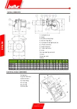
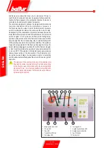
ELECTRICAL CONNECTIONS
The three-phase power supply line must have a switch with fuses. The
regulations further require a switch on the burner’s power supply line,
outside the boiler room and in an easily accessed position. For the
electrical connections (line and thermostats), follow the wiring diagram
enclosed. To carry out the connection of the burner to the power supply
line proceed as follows:
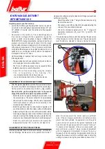
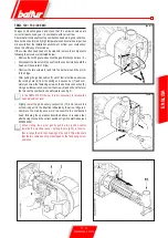
• Remove the lid by unscrewing the 4 screws (1) in figure 1, without
removing the transparent door. In this way the burner’s electrical
panel can be accessed.
• Slacken the screws (2) and, after removing the cable float (3), pass
the two 7 and 4 pole plugs through the hole (see figure 2). Connect
the power supply cables (4) to the contactor, connect the cable to
ground (5) and close the cable holder.
• Reposition the cable float as in figure 3. Turn the cam (6) so that
the float exerts sufficient pressure on the two cables, then tighten
the screws that fasten the cable float. Finally, connect the two 7
and 4-pole plugs.
the housings of the cables for the 7 and 4-pole plugs are
provided respectively for cable Φ 9.5÷10 mm and Φ 8.5÷9 mm;
this ensures that the protection degree is IP 54 (IEC EN60529
Standard) for the electrical panel.
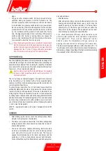
• To close the switchboard cover, tighten the 4 screws (1) to a torque
of approx. 5 Nm in order to ensure proper sealing. Now, to gain
access to the control panel (8), release the clear door (7), by slightly
prising with a tool (e.g. screwdriver) in the direction of the arrows
shown in figure 4, let it slide shortly and then separate it from cover.
• To properly secure the transparent door on the panel again, proceed
as indicated in 5: position the hooks at their hooking points and (9)
slide the door in the direction indicated by the arrow until it clicks.
It is now well sealed.
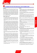
only professionally qualified personnel may open the burner
electrical panel.
Figure 1
Figure 5
Figure 2
Figure 3
Figure 4
Summary of Contents for TBML 80 MC
Page 2: ......
Page 33: ...31 34 0006081545_201305 ENGLISH WIRING DIAGRAM...
Page 34: ...32 34 0006081545_201305 ENGLISH...
Page 35: ...33 34 0006081545_201305 ENGLISH...
Page 67: ...31 34 0006081545_201305 ESPA OL ESQUEMA EL CTRICO...
Page 68: ...32 34 0006081545_201305 ESPA OL...
Page 69: ...33 34 0006081545_201305 ESPA OL...
Page 101: ...31 34 0006081545_201305 ITALIANO T RK E DEUTSCH SCHALTPLAN...
Page 102: ...32 34 0006081545_201305 ITALIANO T RK E DEUTSCH...
Page 103: ...33 34 0006081545_201305 ITALIANO T RK E DEUTSCH...
Page 135: ...31 34 0006081545_201305 T RK E ELEKTR K EMASI...
Page 136: ...32 34 0006081545_201305 T RK E...
Page 137: ...33 34 0006081545_201305 T RK E...
Page 140: ...2 34 0006081545_201305 5 8 SUNTEC 14 15 LME 73 16 17 19 19 21 21 22 24 25 26 28 31...
Page 141: ...3 34 0006081545_201305 BALTUR...
Page 142: ...4 34 0006081545_201305 3 2 RC B...
Page 146: ...8 34 0006081545_201305 5 6 0002934670 3 2 4 1 7...
Page 147: ...9 34 0006081545_201305 10 11 12 000293640 65 80...
Page 148: ...0002911090 10 34 0006081545_201305 EN 676 1 2 3 4 5 6 7 1200 8 9 10 11 12 13...
Page 154: ...16 34 0006081545_201305 LME 73 1 EK EK 2 1 2 BCI AZL2 1 TW...
Page 157: ...19 34 0006081545_201305 O K1 9 2800 9 1 2 1 2 1 1 1 000293 1 1 1 2 2 2...
Page 158: ...13 12 acc_reg001 psd TBML 80MC 003 psd 20 34 0006081545_201305 2 13 2 2 CO2 10 13 2...
Page 159: ...1 7 8 2 3 4 5 6 10 9 Display TBML 80 PN GAS L 21 34 0006081545_201305 1 2 3 4 5 3 7 8...
Page 161: ...23 34 0006081545_201305 1 8 1 1 2 LME 73 200 500 1 3 50 C 5 10 C...
Page 164: ...26 34 0006081545_201305 TBML 80 MC 1 2 3 4 5 6 7 8 9 10 4 0002936380...
Page 169: ...31 34 0006081545_201305...
Page 170: ...32 34 0006081545_201305...
Page 171: ...33 34 0006081545_201305...
Page 174: ...2 34 0006081545_201305 5 8 10 11 SUNTEC 14 15 LME 73 16 17 19 19 21 21 22 24 25 26 28 31...
Page 175: ...3 34 0006081545_201305 a b c a b c d e f g...
Page 176: ...4 34 0006081545_201305 3mm 2 RC a b c d e a b a b c d...
Page 180: ...8 34 0006081545_201305 6 5 0002934670 3 2 7 4 1...
Page 181: ...9 34 0006081545_201305 M 10 11 4 12 0002936400 DN65 DN80...
Page 182: ...0002911090 10 34 0006081545_201305 E N 6 7 6 1 2 3 4 5 6 7 1200 kW 8 9 10 11 12 13...
Page 188: ...16 34 0006081545_201305 LME 73 1 EK LED EK LED 1 2 BCI AZL2 1 LED TW...
Page 191: ...19 34 0006081545_201305 O K1 9 1 2 2800 rpm 9 000293 13 CO2 10 13...
Page 192: ...13 12 acc_reg001 psd TBML 80MC 003 psd 20 34 0006081545_201305...
Page 193: ...1 7 8 2 3 4 5 6 10 9 Display TBML 80 PN GAS L 21 34 0006081545_201305 1 2 3 L E D 3 4 5 3 7 8...
Page 195: ...23 34 0006081545_201305 UV UV UV UV UV UV LME 73 200 500 1 1 50 C 5 10 C...
Page 198: ...26 34 0006081545_201305 TBML 80 MC 1 2 3 4 5 6 7 8 9 10 4 0002936380...
Page 199: ...27 34 0006081545_201305 TBML 120 160 200 MC 1 2 3 4 5 6 7 8 9 3 TBML 200 MC 10 4 0002936380...
Page 203: ...31 34 0006081545_201305...
Page 204: ...32 34 0006081545_201305...
Page 205: ...33 34 0006081545_201305...
Page 207: ......


