N° 0
00
29
01
62
0
11 / 34
0006081545_201305
ENGLISH
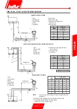
DIESEL OIL SUPPLY LINE
The following description covers merely the basic requirements for
an efficient operation.
The unit is equipped with a self-suction pump, capable of sucking oil
directly from the tank also for the first fill-up. This is true as long as
the required conditions exist, see pipe sizing diagrams. To ensure
efficient operation, it is preferable to make intake and return pipes
with welded fittings and to avoid the use of threaded connections
which often cause air infiltrations and disturb pump operation and
consequently burner operation. Where a removable coupling is
required, use the welded flange method inserting a fuel resistant
gasket to obtain a positive sealing. For systems requiring pipes with
a relatively small diameter we recommend the use of copper pipes.
For unavoidable connections we recommend using “biconic” fittings.
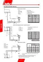
The basic diagrams for the different system types depending on
the position of the tank with respect to the burner are shown below.
The intake pipe should run up-slope towards the burner to avoid
the possible build-up of gas bubbles. Where more burners are
installed in one boiler room, it is essential that every burner has its
own suction pipe.
Only return pipes can lead to a single manifold pipe with an adequate
cross section leading to the tank. Never connect the return pipe
directly to the suction pipe.
It is a good practice to properly heat-insulate the suction and return
pipes to prevent hazardous cooling. Pipe diameters (to be strictly
complied with) are listed in the following tables. The maximum
amount of vacuum that the pump can withstand noiselessly under
normal operating conditions is 35 cm.Hg. ; if these limit is exceeded
normal pump operation will no longer be guaranteed.
Maximum suction and return pressure = 1 bar.
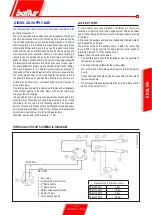
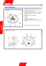
HYDRAULIC CIRCUIT SCHEMATIC DIAGRAM
1 - Foot valve
2 - Air adjustment servomotor
3 - 2
nd
flame nozzle
4 - 1
st
flame nozzle
5 - Safety valve usually closed
6 - Pump (12 bar)
7 - Valve usually closed
AUXILIARY PUMP
In some cases (excessive distance or difference in level) it is
necessary to install a “loop-type” supply system with an auxiliary
pump, thus avoiding the burner pump from being directly connected
to the tank.
In this case, the auxiliary pump can be started with the burner starts
and stopped when it stops.
The electric wiring of the auxiliary pump is made by connecting
the coil (230 V) which controls the pump remote control switch to
terminals 2 (N) and 17 of the printed circuit.
Always follow the instructions below:
• The auxiliary pump should be installed as near as possible to
the liquid to be sucked.
• The head must be suitable for the relative plant.
• We recommend a flow rate equal at least to that of the burner
pump.
• Connection pipes should be sized to cope with the flow rate of
the auxiliary pump.
• Do not connect the auxiliary pump directly to the remote control
switch of the burner motor.
SUCTION
RETURN
Pressure loss in hydraulic circuit
TBML 80 MC
1 bar
TBML 120 MC
1.5 bar
TBML 160 MC
2 bar
TBML 200 MC
2.5 bar
Summary of Contents for TBML 80 MC
Page 2: ......
Page 33: ...31 34 0006081545_201305 ENGLISH WIRING DIAGRAM...
Page 34: ...32 34 0006081545_201305 ENGLISH...
Page 35: ...33 34 0006081545_201305 ENGLISH...
Page 67: ...31 34 0006081545_201305 ESPA OL ESQUEMA EL CTRICO...
Page 68: ...32 34 0006081545_201305 ESPA OL...
Page 69: ...33 34 0006081545_201305 ESPA OL...
Page 101: ...31 34 0006081545_201305 ITALIANO T RK E DEUTSCH SCHALTPLAN...
Page 102: ...32 34 0006081545_201305 ITALIANO T RK E DEUTSCH...
Page 103: ...33 34 0006081545_201305 ITALIANO T RK E DEUTSCH...
Page 135: ...31 34 0006081545_201305 T RK E ELEKTR K EMASI...
Page 136: ...32 34 0006081545_201305 T RK E...
Page 137: ...33 34 0006081545_201305 T RK E...
Page 140: ...2 34 0006081545_201305 5 8 SUNTEC 14 15 LME 73 16 17 19 19 21 21 22 24 25 26 28 31...
Page 141: ...3 34 0006081545_201305 BALTUR...
Page 142: ...4 34 0006081545_201305 3 2 RC B...
Page 146: ...8 34 0006081545_201305 5 6 0002934670 3 2 4 1 7...
Page 147: ...9 34 0006081545_201305 10 11 12 000293640 65 80...
Page 148: ...0002911090 10 34 0006081545_201305 EN 676 1 2 3 4 5 6 7 1200 8 9 10 11 12 13...
Page 154: ...16 34 0006081545_201305 LME 73 1 EK EK 2 1 2 BCI AZL2 1 TW...
Page 157: ...19 34 0006081545_201305 O K1 9 2800 9 1 2 1 2 1 1 1 000293 1 1 1 2 2 2...
Page 158: ...13 12 acc_reg001 psd TBML 80MC 003 psd 20 34 0006081545_201305 2 13 2 2 CO2 10 13 2...
Page 159: ...1 7 8 2 3 4 5 6 10 9 Display TBML 80 PN GAS L 21 34 0006081545_201305 1 2 3 4 5 3 7 8...
Page 161: ...23 34 0006081545_201305 1 8 1 1 2 LME 73 200 500 1 3 50 C 5 10 C...
Page 164: ...26 34 0006081545_201305 TBML 80 MC 1 2 3 4 5 6 7 8 9 10 4 0002936380...
Page 169: ...31 34 0006081545_201305...
Page 170: ...32 34 0006081545_201305...
Page 171: ...33 34 0006081545_201305...
Page 174: ...2 34 0006081545_201305 5 8 10 11 SUNTEC 14 15 LME 73 16 17 19 19 21 21 22 24 25 26 28 31...
Page 175: ...3 34 0006081545_201305 a b c a b c d e f g...
Page 176: ...4 34 0006081545_201305 3mm 2 RC a b c d e a b a b c d...
Page 180: ...8 34 0006081545_201305 6 5 0002934670 3 2 7 4 1...
Page 181: ...9 34 0006081545_201305 M 10 11 4 12 0002936400 DN65 DN80...
Page 182: ...0002911090 10 34 0006081545_201305 E N 6 7 6 1 2 3 4 5 6 7 1200 kW 8 9 10 11 12 13...
Page 188: ...16 34 0006081545_201305 LME 73 1 EK LED EK LED 1 2 BCI AZL2 1 LED TW...
Page 191: ...19 34 0006081545_201305 O K1 9 1 2 2800 rpm 9 000293 13 CO2 10 13...
Page 192: ...13 12 acc_reg001 psd TBML 80MC 003 psd 20 34 0006081545_201305...
Page 193: ...1 7 8 2 3 4 5 6 10 9 Display TBML 80 PN GAS L 21 34 0006081545_201305 1 2 3 L E D 3 4 5 3 7 8...
Page 195: ...23 34 0006081545_201305 UV UV UV UV UV UV LME 73 200 500 1 1 50 C 5 10 C...
Page 198: ...26 34 0006081545_201305 TBML 80 MC 1 2 3 4 5 6 7 8 9 10 4 0002936380...
Page 199: ...27 34 0006081545_201305 TBML 120 160 200 MC 1 2 3 4 5 6 7 8 9 3 TBML 200 MC 10 4 0002936380...
Page 203: ...31 34 0006081545_201305...
Page 204: ...32 34 0006081545_201305...
Page 205: ...33 34 0006081545_201305...
Page 207: ......


