background image

PAGE 90 

W i n d o w s   P C   S o f t w a r e

5.7.3

Submenu Presets

Via 

Presets

 you can save, load and edit configuration presets.

5.7.3.1

Save as ...

Via the option 

Save as ...

, the current configuration can be saved as 

Preset

under any name (max. 8 characters). Special characters and space characters
are 

not

 allowed. Please make sure that you use clear-cut names, otherwise an

error message is displayed asking you if you want to overwrite the already ex-
isting preset.

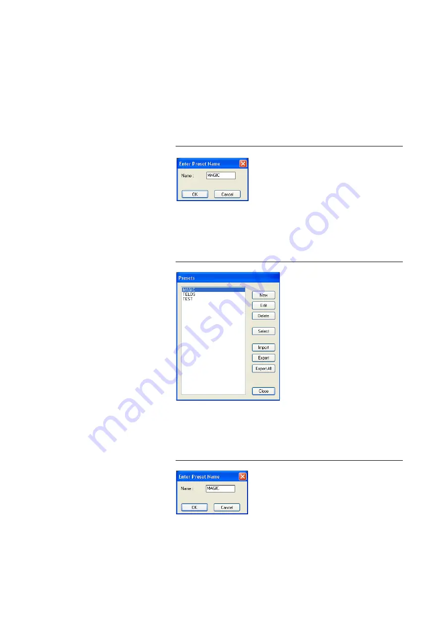
FIG. 55

SAVE PRESET

5.7.3.2

Manage Presets

You can manage your 

Presets

 via the menu

 Configuration 

 Presets 

Manage Presets

.

FIG. 56

MANAGE PRESETS

In the list, all already created configuration presets are displayed.

With the 

New

 button, a new configuration can be created. The current config-

uration of the system is not changed or loaded. First enter a reasonable name. 

FIG. 57

CREATE NEW PRESET

Summary of Contents for MAGIC AC1

Page 1: ...MAGIC DC7 Dual 7 kHz Audio Codec MAGIC AC1 ISDN Audio Codec Hardware Software Manual ...

Page 2: ... ...

Page 3: ... To get always information on the latest software please register on our Homepage http www avt nbg de First click on the menu item Service and then select Software Registration Please select as product MAGIC DC7 or MAGIC AC1 and enter your contact details You need to indicate a valid email address at least ...

Page 4: ......

Page 5: ...Germany Phone 49 911 5271 0 Fax 49 911 5271 100 Printed in Germany August 2012 AVT Audio Video Technologies GmbH All rights reserved Reproduction in whole or in parts is prohibited without the written consent of AVT Audio Video Technologies GmbH Subject to changes Release date 08 12 ...

Page 6: ... ...

Page 7: ... modes of the system 21 3 5 1 Analogue POTS operation 21 3 5 2 ISDN operation 22 4 OPERATION VIA DISPLAY AND KEYPAD 23 4 1 Basic configuration 23 4 1 1 Keypad lock 23 4 1 2 Setting the menu language 23 4 1 3 Setting the operating mode Analogue POTS or ISDN 24 4 1 4 Setting the Audio interface Analogue or digital 24 4 2 Working with MAGIC DC7 AC1 26 4 2 1 Calling a partner 26 4 2 2 B channel connec...

Page 8: ...5 6 2 Submenu Operation Settings Presets 48 5 6 3 Submenu User Transmission Modes 48 5 6 4 Submenu System Settings 48 5 6 5 System Log File 49 5 6 6 Submenu Exit 50 5 7 Menu Configuration 51 5 7 1 Submenu COM Port 51 5 7 2 Submenu MAGIC DC AC1 52 5 7 2 1 Operation Settings 52 5 7 2 1 1 Line Interface 52 5 7 2 1 2 Data Interfaces 57 5 7 2 1 3 Backup 58 5 7 2 1 4 Functions in the main window with ac...

Page 9: ...Mixer 103 5 9 3 Submenu S0 Monitor 104 5 10 Menu Help 105 5 10 1 Submenu About MAGIC DC7 AC1 105 6 OPTION MAGIC DC7 AC1 KEYPAD 107 6 1 MAGIC DC7 AC1 Keypad Basic 107 6 2 MAGIC DC7 AC1 Keypad Advanced 108 6 3 Functions of the Keypad 109 6 4 ISDN alarm messages in the display 113 7 OPTION MIXER TOOL PLUG IN 115 8 OPTION REMOTE CONTROL SOFTWARE 117 8 1 Remote configuration of a MAGIC DC7 AC1 System 1...

Page 10: ...et Micro Audio interface 145 A5 5 Power supply interface 146 A6 TECHNICAL DATA MAGIC DC7 AC1 147 A7 TECHNICAL DATA MAGIC DC7 AC1 KEYPAD 148 A7 1 Keypad 148 A7 2 LCD Display 148 A7 3 Connecting cable 148 A7 4 Connection to power supply 1 149 A7 5 Connection to MAGIC DC7 AC1 2 149 A7 6 Data connection to Keypad 3 149 A7 7 External power supply 150 A8 GENERAL 151 A8 1 Ordering numbers 151 A8 2 Scope ...

Page 11: ... The configuration of the system can be carried out via the Windows applica tion software included in delivery or via the front keypad of the unit Option ally the MAGIC DC7 AC1 Keypad is available for separate operation without PC English Deutsch Menu Select System Settings System Settings Language Language Cap Ok Save settings Yes No Operation Settings Select Mode ISDN Analogue POTS Audio Audio S...

Page 12: ...PAGE 12 I n t r o d u c t i o n Display Delete entry Save as Quick Dial Presets Load New Save Delete Preset Ringing Tone Signal Processing Keypad 9600 none Status information Login Shift ...

Page 13: ...le residual risk to a minimum it is abso lutely necessary to observe the following rules Transport storage and operation of the unit must be under the permissible conditions only Installation configuration and disassembly must be carried out only by trained personnel on the basis of the respective manual The unit must be operated by competent and authorised users only The unit must be operated in ...

Page 14: ...lling in the PC Software TIP The symbol TIP marks information which facilitates the operation of the sys tem in its daily use NOTE The symbol NOTE marks general notes to observe ATTENTION The symbol ATTENTION marks very important advice that is absolutely to observe In case of non observance malfunctions and even system errors are possible ...

Page 15: ... equipped with a module for MPEG Coding The sys tem is designed for mounting in a half 19 rack 1 U Optionally a MAGIC DC7 AC1 DUAL 19 Mounting Kit ID 800212 DC7 and ID 800232 AC1 is available for the installation of two MAGIC DC7 AC1 Systems next to each other FIG 1 FRONT VIEW MAGIC DC7 DUAL 7 KHZ AUDIO CODEC FIG 2 FRONT VIEW MAGIC AC1 ISDN AUDIO CODEC ...

Page 16: ...PAGE 16 C o n s t r u c t i o n ...

Page 17: ...PAGE 17 S y s t e m D e s c r i p t i o n 2 S Y S T E M D E S C R I P T I O N The functional elements of the system are pictured in Fig 3 FIG 3 FUNCTIONAL ELEMENTS MAGIC DC7 AC1 ISDN AUDIO CODEC ...

Page 18: ...s used two separate Sample Rate Converters are available for automatic clock synchronisation For external clocking a clock input and a clock output are available Additionally the Audio Codec incorporates a Headset interface for Stereo tone or Dual Channel tone with a microphone input Limiter and 12V phan tom power which can be switched off By the integrated Audio router all input and output signal...

Page 19: ...tion During operation air humidity must range between 5 and 85 3 2 Connection to the mains voltage The system can be operated with mains voltages in the range from 90 V to 253 V via the external power supply included in delivery The line frequency can vary from 45 Hz to 65 Hz The maximum power consumption is 15W The rack must be earthed according to the VDE Regulations The earthing can be carried ...

Page 20: ... middle there are two cursor buttons upwards downwards two buttons for accepting dropping calls as well as an OK button The numerical pad supports in addition to the numerical char acters 0 9 the and key For text entries the numerical pad can also be used as normal keypad The operation is similar to standard mobile telephones FIG 4 OPERATIONAL ELEMENTS ON THE FRONT SIDE ATTENTION Earthing A lackin...

Page 21: ... telephone line is pic tured in Fig 5 FIG 5 MINIMUM WIRING FOR ANALOGUE POTS OPERATION ATTENTION Earthing If the analogue POTS interface is in operation the system must be earthed via earthing screw for EMC reasons If the earthing is not carried out the Audio signal can be faulty on the caller s side humming Power supply interface POTS telephone interface Analogue Audio 1 left AES EBU Input Analog...

Page 22: ...eypad can be connected as alternative to the operation by the front keypad and display FIG 7 MAXIMUM WIRING FOR ISDN OPERATION Power supply interface ISDN interface Analogue Audio 1 left AES EBU Input Analogue Audio 1 left AES EBU Output Analogue Audio 2 right clock Input Analogue Audio 2 right clock Output Headset Option Power supply PC with Option MAGIC DC7 AC1 Hybrid Keypad MAGIC DC7 AC1 Softwa...

Page 23: ... 2 Setting the menu language In delivery status English is selected as standard menu language To select Deutsch as menu language please follow the instructions below First press the softkey Menu and select System Settings using the softkey Select Press the cursor key once until the option Language is displayed in the menu Via the Select softkey you directly reach the options for the de sired langu...

Page 24: ...gital MAGIC DC7 AC1 incorporates analogue as well as digital Audio interfaces which you can adjust separately The digital AES EBU interfaces have inte grated Sample Rate Converters to adjust the digital Audio source to the trans mission clock Additionally clock inputs outputs are also available To con figure the Audio interface please follow the instructions below First press the softkey Menu and ...

Page 25: ... button or the softkey Ok To get back to the main menu please press the button Now you are asked if you want to Save settings Via the softkey Yes the setting is stored permanently in the system TIP You reach the settings for the Audio input or Audio output via the key se quence Menu 1 1 1 or Menu 1 1 2 ...

Page 26: ...d Audio mode The connection is established by entering the calling number and pressing the phone key Under the softkey Opt Options the entered phone number can be saved in the phone book see CHAPTER 4 3 1 Page 29 or stored as Quick Dial number see CHAPTER 4 3 2 Page 29 4 2 2 B channel connections only in ISDN mode In the ISDN operating mode two independent Audio codecs respectively a Stereo ISO MP...

Page 27: ...d the level indication for the incoming sig nal Receive and for the outgoing signal Transmit is displayed If the Audio connection is synchronised the corresponding Audio coding al gorithm is displayed for each channel T Telephone 3 1 kHz 7 G 722 7 kHz M ISO MPEG Mono S ISO MPEG Stereo no synchronising NOTE If you choose MPEG STEREO only MAGIC AC1 as Audio mode you usually need to enter the phone n...

Page 28: ...n is dropped by pressing the telephone receiver button If no further connection exists the main menu is displayed after a few seconds 4 2 5 Accepting a call If the MAGIC DC7 AC1 receives a call it is automatically signalled in the sta tus window by Callin The call can be directly accepted with the telephone receiver button If you want to reject the call please press the following telephone receive...

Page 29: ...oftkey Select are realised New Entry With the help of this function you create a new phone book en try First enter the name and confirm your entry with Ok Then enter the phone number of the partner and select your desired trans mission mode with the cursor keys and confirm it as well with Ok Edit This function allows you to edit already existing phone book entries Display The selected phone book e...

Page 30: ...certain Preset As soon as you enter a character the corresponding entries of the Preset list are filtered out Alternatively you can select a Preset from the list using the cursor keys and If you now press the Ok button the selected Preset is loaded immediately By the softkey Opt Options the following functions which you can select via the softkey Select are realised Load The stored Preset is loade...

Page 31: ...ate OFF the interface If an interface is acti vated the current level of the Audio source is displayed and can be adjusted with the cursor keys and within the range of 16 dB 16 dB When one of the transmit signal sources e g Source transmit Ch 1 is se lected the option Auto Ducking DCK is additionally available In this config uration the Audio signal of the Audio inputs is treated automatically acc...

Page 32: ...the Headset interface you can adjust the head phones level with the cursor keys and within the range of 40 dB 0 dB during a connection Display connection parameters If the Status key 1 is pressed during a connection the Audio transmission parameters are displayed Display system name If no connection exists you can display the system name by pressing the phone button NOTE When a Stereo transmission...

Page 33: ...s 2000 XP ca 600 kilobyte available RAM 5 MB available hard disk space Screen resolution with 800 x 600 Pixels at least one available serial interface RS 232 Microsoft IBM PS 2 or 100 software compatible mouse 5 2 User Registration To get always information about the latest software automatically please reg ister on our Homepage http www avt nbg de First select the menu item Service and then choos...

Page 34: ... can be started by clicking on the MAGIC DC7 AC1 Please connect your PC via a serial 1 1 cable only Pin 2 and Pin 3 are used Pin 5 ground with the system The standard COM Port settings are PC 19200 Baud 5 4 Software update from the internet Software updates can be down loaded from our homepage http www avt nbg de free of charge Please go o to the Service section on our webpage and select Software ...

Page 35: ...he PC is ok PC OFFLINE or NO CONNECTION connection to the PC is faulty The following status messages are also possible PC ONLINE ALARM an alarm has occurred see System Monitor for alarm message blinking green dark green ISDN REMOTE A remote connection is established blinking red white ISDN REMOTE ALARM an alarm has occurred in the remote system blinking blue dark blue WRONG APPLICATION you are usi...

Page 36: ...thm G 711 G 722 ISO MPEG Layer II III Coding mode Mono Dual Channel Stereo Joint Stereo Sampling frequency 16 kHz 24 kHz 32 kHz 48 kHz the bit rate Rate for the Audio transmission the data Data for J 52 transmissions Gross data rate Net data rate the PAD data rate Program Associated Data in the MPEG data stream Net data rate NOTE If the connection is faulty please check the following points Extern...

Page 37: ... be changed for this transmission are displayed in light grey If the transmission is an ISO MPEG connection the Audio parameters are additionally displayed under MPEG Mode These parameters can also be changed during a connection You can select the ISO MPEG algorithm Algorithm Layer III and optionally Layer II the coding mode and the sampling frequency Additionally you can select if the encoder sho...

Page 38: ...urce is activated blinking in red The Mute function is enabled for the selected channel i e the remote side would hear nothing yellow The Auto Ducking function is enabled see page 77 Depending on the transmission procedure the available levels are displayed Details for the configuration of the Audio mixer can be found under CHAPTER 5 5 3 1 FIG 11 AUDIO MIXER TRANSMIT DIRECTION CALL ACCEPT CONNECT ...

Page 39: ...ion Modes in the soft ware see CHAPTER 5 7 2 2 1 page 64 In the delivery status the following modes are displayed Telephone 7 kHz Auto MPEG 1B Auto MPEG 2B Auto If you configured your own transmission modes see User Defined Trans mission Modes CHAPTER 5 7 2 2 2 Page 68 these modes are also dis played if you click on the transmission mode button With Cancel you can close the context menu without ch...

Page 40: ...function is active Additionally in the Audio mixer MUTED is displayed at the microphone level Headphones output Phones Out Via the button PHONES OUT you select the Audio signals which you want to hear at the headphones if connected Depending on the configuration of the Audio mixer the PHONES OUT but ton can be displayed in the following colours grey No Audio source activated In this case nothing c...

Page 41: ...e monitoring for a signal With Close you can close the window When the Headset Monitor window is opened the MONITOR button is dis played in red to indicate that currently you are not listening to the Audio sig nals which you have selected for the headphones under PHONES OUT see page 40 If the window is closed the button is displayed in grey NOTE If the fee based option Mixer Tool Plug In Order num...

Page 42: ...DIO OUT 1 respectively AUDIO OUT 2 button the window for the selection of the Audio Source for the Audio output is opened Depending on the configuration of the Audio mixer the AUDIO OUT button can be displayed in the following colours grey No Audio source activated In this case nothing can be heard green At least one Audio source is activated blinking in red The Mute function is activated for the ...

Page 43: ... 1 2 Receive Channel 1 2 Microphone Each of these Audio sources has a digital level setting which allows an in creasing or decreasing of the level of 16 dB With the button ON OFF you can activate or deactivate each Audio source for the Audio output device For the Audio output device SEND CHANNEL 1 2 it is possible to activate the Auto Ducking functionality for the Audio source Audio In 1 2 if the ...

Page 44: ...s pressed a confirmation is displayed that the Mixer Preset has been saved successfully FIG 18 MIXER PRESET SAVED To reload a mixer configuration please click on the Mixer Preset button for a second To reset the system to the default settings please click on the SET DE FAULT button The mixer is configured in the following way all levels to 0 dB Receive Channel 1 Audio Out 1 Receive Channel 2 Audio...

Page 45: ...o 20 characters Under Call Mode Number 1 you need to select the transmission mode which is to be used when the entry is called and then enter the calling number If you select a 1 B transmission mode you can configure a second completely independent connection for the second channel Call Mode Number 2 How ever as transmission mode you can only select Telephone or 7 kHz Auto In this way you have the...

Page 46: ...es are deleted by accident you have to confirm your selection FIG 21 CONFIRMATION TO DELETE AN ENTRY With Close you can close the dialogue without any further action To establish a connection with a telephone book entry directly please press CALL NOTE Please notice that the telephone book entries are stored in the system and not on the PC Via the menu File Phone Book Import Export you can also loa...

Page 47: ... 2 JERRY LEE 8 0 160 ULRIKE LAUTERBACH 2 0 141 AVT SUPPORT 0 0 MUSICTAX 123456 DIANA EL TATTAN 1 0 123 WOLFGANG PETERS 0 0 DEMO 130 131 Presets 1 MUSICTAX 17 0201031F016800670069006C007A82980C 1 DEMO 17 0201031F016800670069006C007A829108 Attention The first two lines form the header and must not be missing The lines Presets are only available if you work with Transmission Modes To export a telepho...

Page 48: ...extension of the file is always tmm After clicking on the button the file browser is opened via which the desired file can be selected With Export All you save all already existing User Transmission Modes in a directory of your choice For each mode a file with the extension tmm is generated 5 6 4 Submenu System Settings With the selection File System Settings Import you can import a complete syste...

Page 49: ... The file is saved with the ex tension log The desired directory path can be selected with Browse FIG 24 EXPORTING THE ISDN LOG FILEI The log file can be opened and analysed with the optional ISDN S0 Monitor see CHAPTER 8 2 page 120 NOTE A log file is only generated in the system if the function System Logfile CHAPTER 5 9 1 Page 102 has been activated in the System Monitor ...

Page 50: ...PAGE 50 W i n d o w s P C S o f t w a r e 5 6 6 Submenu Exit Via the submenu Exit you can close the MAGIC DC7 AC1 PC software ...

Page 51: ... desired mode PC Keypad 9600 Baud to connect the Keypad or a PC PC 19200 Baud to connect a PC PC 38400 Baud to connect a PC PC 57600 Baud to connect a PC PC 115200 Baud to connect a PC All further parameters such as Data Bits Parity and Stop Bits cannot be con figured NOTE The MAGIC DC7 AC1 Keypad only supports the baud rate 9600 Baud There fore please select always the setting PC Keypad 9600 Baud...

Page 52: ...tween Basic Settings which usu ally do not have to be changed during the operation and the actual Operation Settings The Operations Settings also include the Transmission Modes Ba sic Settings can not be saved as Preset see CHAPTER 5 7 3 whereas Oper ation Setting can be saved as Preset For clarification A Preset includes all settings made under Operation Settings and Trans mission Modes Various P...

Page 53: ... line a connection is established FIG 27 MAIN WINDOW IN THE LEASED LINE MODE ISDN leased line B1 2 only Same functionality as above except that only B channel 1 B1 or B channel 2 B2 is analysed FIG 28 MAIN WINDOW IN THE LEASED LINE B1 B2 MODE POTS the system is connected to a POTS telephone line In this oper ating mode only one channel is available Therefore an Audio trans mission is only possible...

Page 54: ...lowing settings are only available in the Line Mode POTS If you activated the POTS 50 Hz Filter a disturbing 50 Hz humming is fil tered out The disturbing signal is fed into the system via the POTS line The reason is mostly a wrong cabling of the PABX An Expander turns down the caller signal automatically if its level falls below a certain threshold value The aim is to completely filter out back g...

Page 55: ... one ISDN interface you can allocate a certain calling number to a certain system by entering a MSN Example A telephone an ISDN PC card and a MAGIC DC7 AC1 system unit are operated with one ISDN interface From your provider you got the follow ing MSN 5271011 5271012 5271013 Without a MSN entry all three units respond to the incoming call no matter which of the three calling numbers was dialled How...

Page 56: ...rm that you really want to delete the entry NOTE Some PABX require the entry of a MSN since otherwise no operation is pos sible If you cannot establish a connection between the MAGIC DC7 AC1 system and a partner system but you are sure that the ISDN line is working you should try if it works after entering a MSN NOTE Please consider that only numeric characters which are actually entered are analy...

Page 57: ...any data end devices The transmission is unsymmetrical i e only one wire is used for the transmit and one for the receive channel The procedure is more interference prone and limits the maximum cable length In contrast to this the RS485 interface works with symmetrical transmis sion one pair of wires each for transmit and receive direction whereby the transmission is less interference prone and ca...

Page 58: ...s established as fast as possible The backup is always triggered by the decoder side e g at the transmission site With the selection Encoder you simply switch on the fixed multiplexing scheme Except the Audio Mode no further parameters can be configured The operating mode should be selected if the system is installed e g in the studio With the selection Decoder all available parameters can be conf...

Page 59: ...ime is unlimited Unbackup Block Gate in minutes If a second backup connection is estab lished within the selected time interval the backup connection is not dis connected automatically anymore In this case the backup connection has to be dropped manually by pressing the DROP button or it is dropped after the maximum backup time the latest In this way we want to make sure that a connection which is...

Page 60: ...ctivated backup The main window is adjusted according to your configuration if the backup is activated In the operating mode Encoder only the operating elements for the calling number entry and the selection of the transmission type is displayed The Info field indicates the Backup Encoder configuration In the operating mode Decoder the same operating elements do not apply FIG 33 MAIN WINDOW FOR AC...

Page 61: ...PAGE 61 W i n d o w s P C S o f t w a r e Backup Test Via this button a backup test can be done The result is dis played in the information field ...

Page 62: ...P C S o f t w a r e 5 7 2 1 5 Security NOTE This configuration dialogue is only available if the fee based option Security order number 430240 is enabled Details concerning this option can be found under CHAPTER 10 Page 125 ...

Page 63: ...ally Layer II order number 450305 and a data rate of 64 kbit s 1 B For the signalling the most important procedures are available On the second B channel an independent telephone or 7 kHz connection can be established However a second MPEG connection cannot be established MPEG 2B Auto Audio transmission with ISO MPEG Layer III or op tionally Layer II order number 450305 and a data rate of 128 kbit...

Page 64: ... Mode from Telephone Book entry on incomig call is enabled the transmission mode which is saved together with the caller number of the incoming call in the telephone book is loaded automatically see CHAPTER page 39 if the caller is saved in the tele phone book and the number is transmitted TIP In contrast to AutoDynamicSync ADS see CHAPTER A2 page 137 you enforce the transmission mode If you know ...

Page 65: ...de Stereo Joint Stereo Dual Channel Mono and the sampling frequency 16 kHz 24 kHz 32 kHz 48 kHz if only one B channel 64 kbit s is used for an MPEG connection 2 B Mode Under this setting you can configure the Audio mode Stereo Joint Stereo Dual Channel Mono and the sampling frequency1 16 kHz 24 kHz 32 kHz 48 kHz if two B channels 128 kbit s are used for an MPEG connection TIP Since some Audio code...

Page 66: ...ata channels is not completely defined they usually work only between systems from the same manufacturer 1 The transmission of Ancillary Data is currently only possible with ISO MPEG Layer III NOTE Please consider that in this way the full bit rate is no longer available for the Audio signal The Audio quality is reduced depending on the ancillary data rate Special attention should be paid to the f...

Page 67: ...main window Rate actual Audio data rate Data band width J 52 data channel and actual net bit rate x kbit s net PAD actual net bit rate x kbit s net Ancillary Data FIG 35 DISPLAY OF THE BIT RATES IN THE MAIN WINDOW TAB 2 BIT RATE IN THE J 52 DATA CHANNEL Mode Data Channel 1 2 Number of B Channels Bit Rate MPEG Audio Bit Rate Data Channel LOW 1 56 kbit s 6 4 kbit s 2 112 kbit s 12 8 kbit s HIGH 1 48...

Page 68: ...if the selected transmission mode is to be displayed in the PC Software or and in the front display of the sys tem If you display too many entries the selection of the transmission mode becomes very unclear for the user especially when using the front display therefore you should not display modes that are not required Under Name the name of the transmission mode is displayed The length of a name ...

Page 69: ...all modes on a data carrier please use the function Export All and select the desired target directory Each mode is saved in a separate file If you create a new transmission mode or if you edit an existing one the con figuration dialogue is displayed FIG 38 CONFIGURATION DIALOGUE USER DEFINED TRANSMISSION MODES Transmission Type First select the transmission type for Connection 1 Under Signalling ...

Page 70: ...ect the Audio quality for the transmit di rection Depending on the selectedTransmission Type the following set tings are available G 722 7 kHz MPEG 15 kHz The Audio quality in receive direction Audio Quality RX can only be se lected for the transmission type J 52 since all other procedures only allow a symmetrical Audio transmission The following options are available3 G 722 7 kHz MPEG 15 kHz The ...

Page 71: ... Same settings as under Transmission Modes Data Channel 1 2 J 52 see page 66 3 If you select G 722 7 kHz the system signals to the remote side that only a 7 kHz Decoder is available although you have an MPEG Decoder with MAGIC AC1 In this way the remote side is forced to encode with 7 kHz TIP Since some Audio codecs only allow the same parameters in transmit and re ceive direction this setting sho...

Page 72: ... backlight is automatically turned off 60 seconds after the last keystroke The backlight can be activated again by pressing any key e g OK With the slide controller Contrast you can set the desired contrast for the display within the range of 16 15 The default setting is 0 NOTE All settings made under Basic Settings cannot be saved as Preset see CHAPTER 5 7 3 3 NOTE Please notice that if the key l...

Page 73: ...System Name Under System Name you can enter a name for the system The name is dis played in the optional software plug in MAGIC DC7 AC1 LAN see CHAPTER 9 which allows a simultaneous control of up to 10 systems Toggle Mixer Presets on Call Accept Button The function Toggle Mixer Presets on Call Accept Button allows a fast switching between maximum three Mixer Presets by pressing the button on the f...

Page 74: ...nder Clock Source of digital output the following settings are available Internal The AES EBU output clock is adapted to the internal system clock External The AES EBU output clock is adapted to the external clock which is supplied by the Audio 2 CLK IN interface The clock fre quency of the supplied clock needs to be 48 kHz Recovered The AES EBU output clock is recovered from the digital input sig...

Page 75: ... 1 dB The head room is 6 dB If you want to have the maximum level of 15 dBu for the system you need to set 9 dBu as main nominal level The default setting is 0 dBu Audio Level Offset Via the scroll bar Audio Level Offset you can adjust the Audio Output signal within the range of 16 15 dBu digitally in 1 dB steps The de fault setting is 0 dBu NOTE Changing the Audio Level Offset is only seldom requ...

Page 76: ...e reports of commentators or translations of interpreters For example the original signal of the speaker e g via Au dio 1 Input or Channel 1 Rx is available on the left channel and the inter preter s own translated signal e g via Microphone Input is available on the right channel for checking purposes Microphone Under Microphone you configure the microphone input of the headset inter face If your ...

Page 77: ... setting you select the threshold value at which the re ducing of the Audio input level starts Available range 32 0 dB in 1 dB steps Default setting 20 dB Level This setting defines the level to which the Audio input level is to be reduced Available range 32 0 dB in 1 dB steps Default setting 32 dB Fade Out Speed Here you select the speed with which the Audio input signal is turned down Available ...

Page 78: ...can program a delay for the disconnection within the range of 0 127 sec onds If you select 0 the connection is dropped immediately This setting is helpful e g if you realised an automatic dialling via VOX control If nobody is speaking the connection would be dropped immedi ately by default If you have set a delay short breaks in the speech Audio signal do not result in an immediate disconnection T...

Page 79: ...on is to be established only in the ISDN operating mode Under Trans mission Mode you select the desired mode for the transmission Call Number level triggered Same function as above however except that here the level is analysed and not the edge Disconnect Disconnect By enabling this function a connection on the indicated line 1 or 2 can be disconnected 1 Except function code Call Number level trig...

Page 80: ...g Command Special function for projects Example With TTL1 a call is to be accepted on line 1 The system is to be config ured automatically to the MPEG 1B Mode After the conversation is over the connection is to be dropped also with TTL1 Programming Positive edge Function Code Call Number Line 1 Transmission Mode MPEG 1B Phone Number Negative edge Function Code Disconnect Line 1 FIG 46 FUNCTION SEQ...

Page 81: ...e select the desired connection state under Connection State The following options are available Disconnect Call Out Call In Connect Call Setup Under Line you can select for which line you want to signal the connection state In addition to line 1 and line 2 you can monitor the connection status of both lines if you select all As soon as one of the two lines meets the cri teria the signal is trigge...

Page 82: ...e status of the Pin is transmitted Inverted Remote TTL Input Same function as above except that here the inverted signal is transmitted Remote PC Controlled Special function for projects MPEG Decoder synced If the ISO MPEG Audio decoder is synchro nised the TTL Pin is set Backup Established If you activated the Backup function of the system see CHAPTER 5 7 2 1 3 page 58 you can signal the backup s...

Page 83: ...e identical with the function codes for the TTL output The following options Function Codes are avail able Always open The relay contacts are always open Always closed The relay contacts are always closed All further function codes are explained under TTL Pin as Output Page 81 ATTENTION Please consider that the maximum switching current is 200 mA and the max imum switching voltage is 48V per relay...

Page 84: ...ll is accepted automatically even if the automatic answer of calls is not enabled see Page 54 Enable Auto Answer If this function is not supported by the ISDN connection the password check is not done before the connection has been established A call to the system which is to be controlled remotely must be accepted manually if the automatic answer of calls is not activated see Page 54 En able Auto...

Page 85: ...isting entries With Delete an entry can be deleted For safety reasons you must confirm that you really want to delete the entry NOTE Please consider that only numerical characters which are actually entered are analysed i e if you only enter 130 all participants with a calling number which ends with 123 are allowed to call the system The total character length of all entered telephone numbers must...

Page 86: ...f the front display The quick dial keys can be programmed via the menu Quick Dial FIG 51 QUICK DIAL Please assign an already existing Phone Book entry to a key or define a new Number with a selected Transmission Mode see Chapter 5 7 2 2 1 page 64 NOTE The quick dial functionality can only be used on the system The PC Software has no quick dial keys ...

Page 87: ...button Transmit User Defined Time allows you to set a different time This function is helpful if you want to use the system later on e g in a differ ent time zone FIG 52 DATE AND TIME ATTENTION During a power breakdown the integrated system clock is buffered by an in ternal batterya The life time of a battery is typical ca 7 years The replace ment should only be done by the AVT Service a Type 3V L...

Page 88: ...assigned a password a Login window is automatically dis played when you click on a menu which is protected by the password Please enter the user or the administrator password there FIG 54 PASSWORD LOGIN The user and administrator rights are allocated in the following way 1 Only Administrator Password configured Password is required for changes in the configuration Immediately available menus ATTEN...

Page 89: ... System Monitor User and Administrator Password configured A password is always required Immediately available menus Extras System Monitor User Password is entered Under Configuration Configuration Login only the USER Password can be changed With Configuration Presets the desired preset can be loaded Administrator Password is entered All menus are available NOTE Please notice also the effect on th...

Page 90: ...that you use clear cut names otherwise an error message is displayed asking you if you want to overwrite the already ex isting preset FIG 55 SAVE PRESET 5 7 3 2 Manage Presets You can manage your Presets via the menu Configuration Presets Manage Presets FIG 56 MANAGE PRESETS In the list all already created configuration presets are displayed With the New button a new configuration can be created T...

Page 91: ...onfiguration which is currently se lected in the list The current configuration of the system is not changed or loaded With the Delete button you can delete the configuration which is currently se lected A confirmation is required FIG 59 CONFIRMATION TO DELETE A PRESET To activate a configuration selected from the list please press the Select but ton A confirmation is required FIG 60 CONFIRMATION ...

Page 92: ...ired stor age location can be selected with Browse FIG 61 EXPORT A PRESET With Export All you can save all configurations displayed in the list in a di rectory of your choice For each configuration an individual file with the ex tension pst is generated 5 7 3 3 Activate a Preset All Presets are displayed under Configuration Presets Preset Name and can be activated by simply clicking on them FIG 62...

Page 93: ... are displayed Under the DSP Module tab you find the features for the DSP Module only MAGIC AC1 Under Features all available Software Options are listed Upgrade of Firmware Options To activate further Firmware Options at a later time please enter the pass word which you received from us in the dialogue which opens when you click on the button Enter Password FIG 65 PASSWORD ENTRY NOTE For an Upgrad...

Page 94: ... you send us e g by email to sup port avt nbg de we can activate the Upgrade Afterwards we send you the file LicenceUpdate v2c which you can load to your system by clicking on the Update USB Dongle button Now the new function is available NOTE The submenu USB Dongle Information is only displayed if the USB Dongle for fee based options is connected to the PC NOTE Please consider that we differentia...

Page 95: ...ote Control Further details concerning the function Remote Control can be found under CHAPTER 8 Page 117 NOTE The submenu Remote Control is only available if the fee based Option Re mote Control Software see CHAPTER 8 is enabled and the USB dongle is plugged in ...

Page 96: ... from the system to the connected PC ATTENTION Please do not carry out any actions under File System unless our support asked you to All user import export functions can be found under the menu File see CHAPTER 5 6 ATTENTION Do not delete a file unless our service told you to delete the file Otherwise a malfunction of the system can occur ATTENTION Please use only the function Firmware Download se...

Page 97: ...W i n d o w s P C S o f t w a r e 5 8 5 Submenu System Panel The System Panel is only for service purposes Please only enter commands in the prompt if our support asked you to do so FIG 68 SUBMENU SYSTEM PANEL ...

Page 98: ...ion directory is C Programme MAGIC DC7 AC1 The name of the firmware file is ac1 ssw FIG 69 FIRMWARE DOWNLOAD Please press the Start button to load the firmware on your system The Pro gress bar shows the status of the download After about three minutes the download will be finished If the download had been successful a message is displayed After a confirmation the system executes a reset NOTE If a ...

Page 99: ...esets by selecting the submenu Create 15 kHz Telephone Mixer Presets Since already existing mixer presets are overwritten by this action a warning is displayed FIG 70 WARNING WHEN MIXER PRESETS ARE CREATED If you agree to create the presets YES the Mixer Presets Handset and Audio are created The switching between the two Mixer Presets during a connection is made by pressing the button Please assig...

Page 100: ...ry Settings Via the submenu Factory Settings all settings are reset to the factory settings For safety reasons a confirmation is required FIG 71 CONFIRMATION TO SET FACTORY SETTINGS NOTE The telephone book Presets Transmission Modes and Mixer settings are not deleted ...

Page 101: ... keeper is faulty A D D A Converter 1 The communication with the first AD DA Con verter is faulty A D D A Converter 2 The communication with the second AD DA Converter is faulty MPEG Encoder DSP error The communication with the DSP module is faulty only MAGIC AC1 Temperature Sensor The communication with the temperature sen sor is faulty FLASH EPROM The communication with the non volantile memory ...

Page 102: ...d A normal DSP load is 30 60 Under System Logfile a detailed ISDN logfile can be generated ISDN Layer 1 Physical Layer All messages which concern the phys ical activation deactivation of the ISDN interface are saved in Layer 1 ISDN Layer 2 Data Link Layer The Data Link Layer is responsible for packing the data from the physical layer into frames It can detect and or correct errors and manages the ...

Page 103: ...Audio level can be adjusted individually within the range of 16 16 dB FIG 73 AUDIO MIXER OVERVIEW The MUTE function is available for each Audio source and each Audio output device separately Likewise all Mixer Presets can be selected and controlled With the SET DEFAULT button the mixer is reset to the default settings all levels to 0 dB Receive Channel 1 Audio Out 1 Receive Channel 2 Audio Out 2 A...

Page 104: ...0 Monitor Further details concerning the functions of the S0 Monitor can be found under CHAPTER 8 2 Page 120 NOTE The submenu S0 Monitor is only displayed if the fee based Option Remote Control Software see CHAPTER 8 is enabled and the USB dongle is plugged in ...

Page 105: ...p 5 10 1 Submenu About MAGIC DC7 AC1 In the About MAGIC DC7 AC1 dialogue you can find the software versions of the PC Software PC Version and of the system Firmware Version Fur thermore you can find our contact information FIG 74 SUBMENU ABOUT MAGIC DC7 AC1 ...

Page 106: ...PAGE 106 W i n d o w s P C S o f t w a r e ...

Page 107: ...llows the user to control the system without a PC and without using the front dis play and keypad NOTE To use the keypad with MAGIC DC7 AC1 you need to configure the inter face parameters of the RS232 interface in the following way 9600 Baud no parity With the Quick Menu function you reach the setting of the RS323 pa rameters directly via the key sequence Menu 1 4 Please select Keypad 9600 none ...

Page 108: ... and the 6 pole Mini DIN female of the external power supply with the 6 pole Mini DIN connector violet of the breakout ca ble The 8 pole Mini DIN connector black or white must be plugged into the socket of the MAGIC DC7 AC1 Keypad If everything is connected correctly the display is now illuminated After switching on the system1 e g the status message on the left hand side is displayed after bootin...

Page 109: ...the display switches between calling number and level meter in the second line The Shift mode is left automatically after the key is pressed Via these keys a telephone book entry can be selected The cursor can be moved up and down in steps of 1 When the SHIFT button symbol in the display is pressed the cursor moves in steps of 5 The Shift mode is left automatically after the key is pressed By pres...

Page 110: ...set is displayed The Shift mode is left automatically after the key is pressed To save an Audio mixer Preset or a quick dial number respectively please use the button Store Preset QD Saving a Preset First please define the desired Audio mixer settings with the buttons for the Audio interface e g Audio Out 1 and the Audio source e g Select RX1 Press the Store Preset QD button The message Store Pres...

Page 111: ...udio source keys dark blue IN1 Audio input signal Audio 1 IN2 Audio input signal Audio 2 MIC microphone signal Please note that several Audio sources can only be selected at the same time for one trans mission if the fee based Option Mixer Tool Plug In see CHAPTER 7 Page 115 is enabled for your system Otherwise the Audio source which you selected most recently is activated Via the Phones button yo...

Page 112: ...llow you to adapt the transmit receive signal level ratio of the head phones within the range of 16 dB 16 dB Via the Phones level buttons you can adjust the headphones level within the range of 40 dB 0 dB With the AUDIO IN level button you can vary the Audio input level within the range of 16 dB 16 dB Via the Micro level button you can adjust the mi crophone amplifier within the range 16 dB 16 dB ...

Page 113: ...ain Normal call clearing The connection has been dropped User busy The remote side is busy No user responding The partner is not responding Maybe the call was made with the wrong service indicator Call rejected The call was rejected Maybe the remote side re jected your call Number changed The number you called has been changed Destination out of order The remote side is not ready Maybe the system ...

Page 114: ...PAGE 114 O p t i o n M A G I C D C 7 A C 1 K e y p a d ...

Page 115: ...order number 430201 allows you to mix all available Audio signals Without this option you can only switch between the Audio output devices and the Audio sources so that only one in put or output respectively is active at a time The Auto Ducking Function is also only available if this option is enabled see Auto Ducking Parameter Page 77 ...

Page 116: ...PAGE 116 O p t i o n M i x e r T o o l P l u g I n ...

Page 117: ...y as well as remotely 8 1 Remote configuration of a MAGIC DC7 AC1 System The remote control function can be activated via the menu Administration Remote Control FIG 76 REMOTE CONTROL Under Settings please enter your own MSN if required The MSN is only necessary if you operate several systems at your ISDN Bus However some PABXs always require the entry of an MSN FIG 77 MSN SETTINGS FOR REMOTE CONTR...

Page 118: ... is displayed see fig ure below Now you can close the Remote Control window FIG 78 REMOTE CONTROL ONLINE The MAGIC DC7 AC1 System can now be controlled and configured as usual Please note that one of the two B channels is busy with the remote control so that the user can only work with one channel The remote side can stop the remote control at any time The main window of the MAGIC DC7 AC1 Software...

Page 119: ... C o n t r o l S o f t w a r e FIG 79 DISPLAY DURING REMOTE CONTROL NOTE For security reasons the settings for Remote Control see CHAPTER 5 7 2 3 5 and Login see CHAPTER 5 7 2 5 are not visible on the remote side and cannot be changed ...

Page 120: ...es between the User Layer 2 and Layer 3 dis play The User view displays a summary of the most important informa tion Of course for experts the options Layer 2 and Layer 3 are also in formative Errors in the log file are displayed red shaded Via the button Go to Error the next error in the log file is displayed The button Reset resets the display window With the use of the Export key the log file c...

Page 121: ...sing Filter you can filter the log file for certain criteria S0 selects the ISDN interface of the system For the MAGIC DC7 AC1 this value must al ways be 0 respectively be empty since the system incorporates only one ISDN interface Using the filter CR Call Reference you can display all available entries for a transaction Additionally the colour in which the entries are displayed is changed for eac...

Page 122: ...PAGE 122 O p t i o n R e m o t e C o n t r o l S o f t w a r e FIG 82 S0 MONITOR LAYER 3 ...

Page 123: ...erial interfaces or via RS232 LAN converters FIG 84 MAIN WINDOW CONTROL OF SEVERAL AUDIO CODECS On the left side of the main window each Audio Codec installed within the network is displayed In the status line the name of the Codec and the PC sta tus is displayed Below two fields inform you about the current connection status of the two available B channels If a connection exists the calling numbe...

Page 124: ... O p t i o n R e m o t e C o n t r o l S o f t w a r e FIG 85 INFO FIELD OF ONE AUDIO CODEC The detailed view and the control and configuration view you reach by click ing on the desired Codec on the left side ...

Page 125: ...t details could be lost By activating the ring buffer the signal is permanently buffered If an event occurs the signal is read out from the ring buffer and transmitted with the corresponding delay In this way no relevant Audio information is lost Audio Transmission Delay at Connection 1 Under Mode please select the desired operating mode for the first connec tion The following modes can be selecte...

Page 126: ... seconds or 6 seconds respectively DTMF Under Enable DTMF pad you can select your system for DTMF control see special manual for MAGIC AC1 Security The control window can be reached during a connection by pressing the Connect button The configuration Preselected Addresses allows you to preselect up to 4 different addresses Address 1 4 for which you can assign addition ally alias names Name 1 4 In ...

Page 127: ...nly Administrator Password configured The password must be en tered for changes to the basic settings and operation settings only Im mediately available menus Presets Status information Login 2 Only User Password configured instead of Menu Login is displayed The password must always be entered Subsequently all menus are available 3 User and Administrator Password configured instead of Menu Login i...

Page 128: ...PAGE 128 M e n u S t r u c t u r e A1 1 System Settings RS232 see next page ...

Page 129: ...PAGE 129 M e n u S t r u c t u r e Continuation System Settings Headset see previous page ...

Page 130: ...PAGE 130 M e n u S t r u c t u r e A1 2 Operation Settings Enc follows Dec see next page ...

Page 131: ...PAGE 131 M e n u S t r u c t u r e Continuation Operation Settings Incoming Call Mode 50 Hz Filter see previous page ...

Page 132: ...PAGE 132 M e n u S t r u c t u r e A1 3 Presets ...

Page 133: ...PAGE 133 M e n u S t r u c t u r e A1 4 Status Information ...

Page 134: ...PAGE 134 M e n u S t r u c t u r e A1 5 Login ...

Page 135: ...PAGE 135 M e n u S t r u c t u r e A1 6 Names ...

Page 136: ...PAGE 136 M e n u S t r u c t u r e ...

Page 137: ...mpling frequency also half sampling frequencies such as 16 kHz and 24 kHz except 22 05 kHz and 44 1 kHz and any mode Mono Dual Channel Stereo Joint Stereo Additionally an inverted ISO MPEG signal is also decoded correctly If a G 722 signal is found instead of an ISO MPEG frame the synchronisation procedures according to H 221 H 242 and SRT Statistical Recovered Timing are supported In this way it ...

Page 138: ...no 24 kHz CDQ Prima MAGIC J 52 MPEG 15kHz MPEG 15kHz 2 MPEG Layer III Mono 48 kHz Joint St 48 kHz MAGIC MAYAH Cen tauri MCJ52 L3 J 52 MPEG 15kHz G 722 7 kHz 2 MPEG Layer III Mono 48 kHz Joint St 48 kHz MAGIC command channel MT064 L3 Musictaxi 1 MPEG Layer III Mono 48 kHz MusicTaxi MT128 L3 Musictaxi 2 MPEG Layer III Mono 48 kHz Joint St 48 kHz MusicTaxi PKI15KHZ J 52 MPEG 15kHz MPEG 15kHz 2 MPEG L...

Page 139: ... in the analogue operating mode Please check if the POTS line is twisted The system must be earthed via the earthing screw There is a humming in the ana logue operating mode Please enable the 50 Hz filter The humming is injected via the POTS connection The Echo Canceller is not work ing If you switch callers via a Call In Centre to the hybrid the Echo Canceller is possibly adjusted incorrectly Ena...

Page 140: ...PAGE 140 I n t e r f a c e s A 5 I N T E R F A C E S The interfaces of the system are pictured in Fig 88 FIG 88 REAR VIEW OF THE MAGIC DC7 AC1 AUDIO CODEC All interfaces are described below ...

Page 141: ...Recommendation I 430 Data rate B channel 2x64 kbit s D channel 16 kbit s 2 not used 3 TX a Data out a 4 RX a Data in a 5 RX b Data in b 6 TX b Data out b 7 not used 8 not used 1 POTS Plain Old Telephone Service TAB 8 PIN ASSIGNMENT ANALOGUE POTS TELEPHONE INTERFACE LINE POTS Socket Western 6 pole RJ12 Pin Signal Electrical characteristics 1 not used Typical characteristics Bandwidth 300 3 3 kHz Si...

Page 142: ... it is always TXD For both data interfaces RXD serves as receive path and TXD serves as trans mit path TAB 9 PIN ASSIGNMENT CTRL DATA INTERFACE Socket SUB D 9 pole Pin Signal Electrical characteristics 1 not used PC interface RS232 Type Pin 2 3 DCEa Level V 24 Data rate 38400 Baud Range max 15 m Protocol 1 start bit 8 data bits 1 stop bit Data interfaces Level V 24 RS232 V 11 RS485 Data rate 38400...

Page 143: ... RELAY INTERFACE TTL RELAY Socket SUB D 9 pole Pin Signal Electrical characteristics 1 5V 300mA output Capacity of the TTL outputs Maximum voltage 5V Maximum current 10mA Capacity of the relays Maximum voltage 48V Maximum current 200mA 2 TTL 1 IN OUT 3 TTL 2 IN OUT 4 TTL 3 IN OUT 5 GND 6 Relay 1a 7 Relay 1b 8 Relay 2a 9 Relay 2b 5 1 9 6 ...

Page 144: ...ock input or output may be used TAB 11 PIN ASSIGNMENT ANALOGUE INPUT AUDIO 1 2 IN Socket 3 pole XLR Pin Signal Electrical characteristics 1 GND Input level adjustable 3 9 dBu Impedance 25 kΩ Head room 6 dB 2 AUDIO IN a 3 AUDIO IN b TAB 12 PIN ASSIGNMENT ANALOGUE OUTPUT AUDIO 1 2 OUT Connector 3 pole XLR Pin Signal Electrical characteristics 1 GND Output level adjustable 3 9 dBu Impedance 50 Ω Head...

Page 145: ... CLOCK OUTPUT CLK OUT Connector 3 pole XLR Pin Signal Electrical characteristics 1 GND TTL 2 CLOCK OUT 3 not used TAB 17 PIN ASSIGNMENT HEADSET MICRO AUDIO INTERFACE Socket 5 pole XLR Pin Signal Electrical characteristics 1 MICROPHONE a 12V phantom power Input level adjustable 3 9 dBu Impedance 25 kΩ Head room 6 dB 2 MICROPHONE b 3 GND 4 HEADSET left channel 5 HEADSET right channel Push 1 2 3 2 1 ...

Page 146: ...5 5 Power supply interface The power supply is connected via an external power supply TAB 18 PIN ASSIGNMENT POWER SUPPLY Socket KYCO KPJ S3 Pin Signal Electrical characteristics 1 GND Voltage 12V Power max 15W 2 12V 3 not used 1 3 2 ...

Page 147: ...PAGE 147 T e c h n i c a l D a t a A 6 T E C H N I C A L D A T A M A G I C D C 7 A C 1 ...

Page 148: ... A C 1 K E Y P A D A7 1 Keypad Matrix 8 x 6 32 keys 4 quad keys 4 double keys 24single keys A7 2 LCD Display 2 x 20 characters illuminated A7 3 Connecting cable FIG 89 CONNECTING CABLE MAGIC SYSTEM KEYPAD Protocol 9600 Baud no parity to MAGIC DC7 AC1 to power supply to Keypad 1 2 3 ...

Page 149: ...MENT DATA CONNECTION TO KEYPAD Connector PS 2 male 6 pin Pin Signal Electrical characteristics 1 Voltage 5V Power max 1500 mA 2 3 GND 4 5V 5 6 Connector 9 pin SUB D male Pin Signal Electrical characteristics 1 Baudrate 9600 Baud Parität keine 2 RXD 3 TXD 4 5 GND 6 7 8 9 Connector MINI DIN male 8 pin Pin Signal Electrical characteristics 1 Baud rate 9600 Baud Parity none 2 RX Data 3 GND 4 5 5V 6 7 ...

Page 150: ... e c h n i c a l D a t a A7 7 External power supply TAB 22 PIN ASSIGNMENT POWER SUPPLY Connector 6 pin PS 2 socket Pin Signal Electrical characteristics 1 Voltage 5V Power max 1500 mA 2 3 GND 4 5V 5 6 1 6 4 2 3 5 ...

Page 151: ...tware Options DC7 Mixer Tool2 430202 DC7 Remote Control Software2 430198 AC1 Mixer Tool3 430201 AC1 Remote Control Software3 430199 A8 2 Scope of delivery MAGIC DC7 or MAGIC AC1 CD Windows PC Software 430227 External power supply Input 100 240V 24W 50 60 Hz Output 12V Self adhesive feet 19 Mounting Brackets Manual 1 also available in the internet under this identity number 2 An ISDN PC card and at...

Page 152: ...PAGE 152 G e n e r a l 1 x S0 cable A8 3 Declaration of Conformity You will find the declaration of conformity at the end of this manual ...

Page 153: ... can contact our Support Hotline during the normal office hours between 09 00h 17 00h under the following telephone number 49 911 5271 160 or via email support avt nbg de To deal with your problem efficiently please note the factory number of the unit as well as the software version that you use A9 3 Repairs If contrary to expectations your unit is defective please fill in the attached status repo...

Page 154: ...PAGE 154 S e r v i c e I n f o r m a t i o n ...

Page 155: ...ature 19 Analogue 21 24 74 Ancillary Data 37 Apply 38 Audio 1 AES IN 74 Audio 2 CLK IN 74 Audio 2 CLK OUT 74 Audio input 24 74 Audio interface 24 74 Audio Line 79 AUDIO OUT 42 Audio output 24 42 74 Audio settings 24 Audio sources 38 Ausgang 81 Authorisation levels 88 Auto 39 Auto Dynamic Sync 39 137 Auto Ducking 38 B B channel 56 141 Backlight 72 Basic configurations 23 Basic Settings 48 52 72 Bau...

Page 156: ...lows Decoder on in coming calls 37 English 72 127 Erdung 26 EURO ISDN 141 Exit 50 Expander 54 Export 46 47 48 49 92 Export All 48 92 External 74 External power supply 36 146 External prefix number 55 Extras 89 F Factory Settings 100 File 47 48 49 File browser 48 92 Firmeware Download 98 Firmware 98 Firmware version 105 Fixed to High 5V 81 Fixed to Low 0V 81 FLASH EPROM 101 Flash memory 98 Front vi...

Page 157: ...9 23 Menu structure 23 127 Microphone 40 Minimum requirements 33 Mixer Presets 48 Mode 51 MONITOR 41 Mounting brackets 19 MPEG 1B Auto 39 MPEG 2B Auto 39 MPEG Mode 37 MSN 55 117 MSN 1 56 MSN 2 56 Mute 38 40 42 MUTE MICRO 40 Mute microphone 32 MUTED 40 N Name 45 Names 29 127 Navigation 120 Negative edge 79 Network Layer 102 NEW 45 New 30 90 New entry 29 Number 45 Numerical keys 29 O OFF 41 Office h...

Page 158: ...ick Dial 29 Save Preset 37 Save settings 24 Scope of delivery 141 151 Search 29 45 Select 23 91 SEND CH 38 Serial cable 34 Service 33 service purposes 97 Set Audio Line 80 Settings 117 Setup 34 SHIFT 27 29 Skip prefix number 55 Softkey 20 23 Software 23 153 Software Registration 33 Software Updates 153 software version 105 Space characters 90 91 Special characters 90 91 SRT 137 Standby mode 19 Sta...

Page 159: ...ransmission Type 37 Transmit 27 Transmit direction 38 Transport 13 TTL 78 81 83 143 TTL1 78 TTL2 78 TTL3 78 U Updates 153 USB 151 USB stick 48 92 USER 88 User 127 User Defined 37 User Defined Transmission Mo des 39 User Password 88 89 User rights 88 V Ventilation 19 Version 105 Voltage 81 W Warranty claim 19 Wiring 21 22 ...

Page 160: ...PAGE 160 I n d e x ...

Page 161: ...tung folgender Normen The conformity is evidenced by strictly meeting the following standards Harmonisierte Normen EN 55022 EN 55024 Harmonized Standards EN 300386 FCC Part 15 B Ort Datum Nürnberg 24 03 2005 Place date Name n Wilfried Hecht Name Rechtsverbindliche Unterschrift en Legally binding signatures Telefon 49 911 5271 0 Phone Diese Erklärung beinhaltet keine Zusicherung von Eigenschaften T...

Page 162: ...SEITE 162 ...

Reviews: