Electrical Installation
15
Avaya
t
RS9 UPS (9–18 kVA, 9-Slot Models) Site Preparation, Installation and Operator’s Manual
S
164201543 Rev A
5.
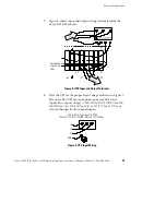
Figure 8 shows input and output wiring terminals inside the
Avaya RS9 UPS cabinet.
3
2
1
+DC
X1
X2
N
-DC
N
-DC
X2
+DC
X1
Backplane Board
Terminating
Studs
Figure 8. UPS Input and Output Terminals
6.
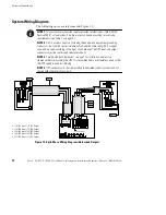
Wire the UPS for the proper input voltage as shown in Figure 9.
The Avaya RS9 UPS uses split-phase power modules that
supply two output voltages: 100/100 for 200, 110/110 for 220,
120/120 for 240, 120/120 for 208, or 127/127 for 220 Vac, as
selected through the front panel display.
(3-Wire Plus Ground Input) (2 PEN)
100/200, 110/220, 120/208, 120/240, 127/220 Vac
3
2
1
L2
L1
N
GND
Figure 9. UPS Input Wiring


