


Electrical Installation
18
Avaya
t
RS9 UPS (9–18 kVA, 9-Slot Models) Site Preparation, Installation and Operator’s Manual
S
164201543 Rev A
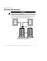
System Wiring Diagram
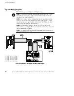
The following notes are referenced in Figure 12.
NOTE 1
The customer must provide input overcurrent protection as stated in NEC
Section 240-21 or local codes. Size the protection device according to local code
requirements (see Table 1 on page 12).
NOTE 2
All AC circuit conductors, including the neutral and equipment grounding
conductors, must be the same size (ampacity), have the same rating (75°C) copper
wire, and be sized according to the input circuit breaker. The UPS input and output
conductors must be run through separate conduits.
NOTE 3
See “Equipment Clearances” on page 7 for installation and service
clearances before installing the UPS. It is recommended to use flexible conduit so that
the UPS can be moved for servicing.
NOTE 4
UPS output circuits shall be installed in dedicated conduit systems and not
shared with other electrical circuits.
S
110/220 Input, 110/220 Output
S
120/208 Input, 120/208 Output
S
120/240 Input, 120/240 Output
S
100/200 Input, 100/200 Output
S
127/220 Input, 127/220 Output
NOTE 1
NOTE 2
NOTE 2
NOTE 3
NOTE 4
NOTE 4
Figure 12. Split-Phase Wiring Diagram (Hardwired Output)


