background image

Troubleshooting

54

Avaya

t

RS9 UPS (9–18 kVA, 9-Slot Models) Site Preparation, Installation and Operator’s Manual

S

164201543 Rev A

Answer

Question:

How do I...

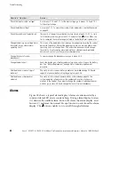
Check the input or output voltage?

Go to menus 1-1-2 and 1-1-3 for the input voltage; go to menus 1-2-2 and 1-2-3
for the output voltage.

Check the battery voltage?

Go to menu 1-3-1. To view other system status parameters, see the Menu map
on page 40.

Check the condition of the batteries?

The results of the most recent battery test are stored at menu 3-1-2-1. To run a
test of battery condition, go to menu 3-1-1 and press the

button. When the

test is complete, the results are again stored in the Battery Results parameter.

Change the battery low-voltage alarm
threshold? (or any other alarm or
operating limit?)

This is one of the parameters that require a trained person, knowing the correct
password, to perform. Without the proper password, you are only able to view
operating limits, not change them. Only authorized personnel should change
these limits. For information about making this or other password-protected
adjustments, contact your Avaya service representative.

Change the level of system
redundancy?

To view or change the redundancy level, go to menu 4-2-5.

Change the batteries?

Each side-by-side pair of battery modules forms one series string on the battery
bus. See “Battery Replacement” on page 46 for the battery replacement
procedure.

Add/delete one or more strings of
batteries?

Physically install or remove battery modules as described on page 24. Record
capacity of external battery strings by going to menu 4-2-6.

Add/delete one or more power
modules?

Physically install or remove power modules as described on page 24. The
system operating software senses the number and location of all power
modules in the cabinet. If you want to change the number of redundant power
modules, go to menu 4-2-5 and change the level of system redundancy.

Alarms

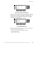
Figure 28 shows a typical alarm display. Alarms are annunciated by a
constant Alarm LED and a constant beep. During alarm display, button
(A) silences the audible alarm, button (B) clears the alarm display, and
button (C) performs the normal Escape function to exit from the alarm
display. The

button enables you to scroll through all alarms.

Summary of Contents for RS9

Page 1: ...Avaya RS9 Uninterruptible Power Systems 9 18 kVA 9 Slot Models Site Preparation Installation and Operator s Manual www avayaups com ...

Page 2: ......

Page 3: ...Avaya RS9 Uninterruptible Power Systems 9 18 kVA 9 Slot Models Site Preparation Installation and Operator s Manual www avayaups com ...

Page 4: ...generates uses and can radiate radio frequency energy and if not installed and used in accordance with the instruction manual may cause harmful interference to radio communications Operation of this equipment in a residential area is likely to cause harmful interference in which case the user will be required to correct the interference at his own expense ICES 003 This Class A Interference Causing...

Page 5: ...nts 7 UPS Setup 8 Moving the Cabinets 9 3 Electrical Installation 11 Input Current Ratings 12 UPS Installation 13 System Wiring Diagram 18 4 Battery Cabinet Installation 19 5 UPS Startup 23 Power and Battery Module Installation 24 UPS Startup 25 Initial Startup Parameters 27 6 Operation 31 Turning the UPS On 32 Removing Input Power 33 Front Panel Display 33 Using the Front Panel Display 34 Paramet...

Page 6: ... Management Software 41 Optional Internal Web SNMP Card 42 Optional Relay Card 42 Communication Slots 42 Dedicated Input Signals 43 DB 9 Communication Port 44 8 Maintenance 45 Storage Temperature 46 Battery Replacement 46 Power Module or Battery Charger Module Replacement 47 9 Specifications 49 10 Troubleshooting 53 Alarms 54 Obtaining Service 59 Parts List 59 ...

Page 7: ... senses problems in power modules and automatically transfers control and load to the remaining power modules All power modules share the load requirements equally For example three power modules are capable of supplying a total of 9 kVA If a load requires only 4 5 kVA each power module supplies 1 5 kVA to the output If one power module is removed or for some reason fails each of the two remaining...

Page 8: ...ules The battery charger module operates in automatic modes within the UPS cabinet under control of the UPS power modules It communicates through a controller area network CAN bus with the power modules The power modules monitor and control the battery charger Alarm conditions detected by the battery charger module are logged and announced by the UPS system see Alarm Log on page 38 Normal output v...

Page 9: ...put and output power conductors to values specified in Table 2 on page 12 S The user is required to provide power input and output disconnect devices for the UPS These must be within sight of the UPS and easily accessible Physical Features Figure 1 shows the 9 slot UPS cabinet and identifies basic Avaya RS9 system features A 9 slot External Battery Module Cabinet is also available Front Panel Disp...

Page 10: ...ot Models Site Preparation Installation and Operator s Manual S 164201543 Rev A Communication Slots Entrance Panel Figure 2 9 Slot Cabinet Rear View Handle Latch Release Insertion Extraction Cams Handle Thumbscrew Figure 3 Power Module 700248974 ...

Page 11: ...els Site Preparation Installation and Operator s Manual S 164201543 Rev A Handle Latch Release Insertion Extraction Cams Handle Thumbscrew Figure 4 Battery Charger Module 700249030 Secondary Stop Release Latch Release Figure 5 Battery Module 700248982 ...

Page 12: ...Introduction 6 Avayat RS9 UPS 9 18 kVA 9 Slot Models Site Preparation Installation and Operator s Manual S 164201543 Rev A ...

Page 13: ...e service input and load distribution panels you may be able to gain access for servicing by moving the UPS If this is the case you must still leave 12I 30 5 cm clearance at the back and 6I 15 2 cm at the sides of the UPS for ventilation NOTE Do not block the ventilation holes on each side and the back of the unit Location Requirements Install the Avaya RS9 UPS as close as possible to the equipmen...

Page 14: ... of the cabinet base by using a 1 2I hex style socket wrench to turn each bolt clockwise 2 With all casters fully extended carefully roll the cabinet down the ramp and to its intended operating location 3 Turn all four caster bolts counter clockwise until the cabinet rests on the floor Place a plastic cap into each bolt access hole NOTE If the floor is uneven and the cabinet is tilted or unstable ...

Page 15: ...on its casters 1 Ensure that the cabinet contains no power or battery modules 2 Locate the four plastic caps covering the caster bolts at the corners of the cabinet base 3 Pry the caps out of the bolt access holes 4 Use a 1 2I hex style socket wrench to turn each of the four bolts clockwise Doing so lowers the casters to allow the cabinet to roll on the casters 5 After rolling the cabinet to its i...

Page 16: ...Installation Setup 10 Avayat RS9 UPS 9 18 kVA 9 Slot Models Site Preparation Installation and Operator s Manual S 164201543 Rev A ...

Page 17: ...nsed electrician MUST perform the electrical installation Risk of electrical shock The UPS input must be hardwired through conduit to a main power source circuit breaker The UPS output may be hardwired to a circuit breaker in a distribution panel as shown in Figure 6 Building Service Panel Load Distribution Panel User supplied If Required External Batteries Optional Figure 6 Avaya RS9 Typical Inst...

Page 18: ...ring to support a 18 kVA unit See Table 2 for recommended conductor size to wire the input circuit breaker Table 2 Recommended Wire Sizes Input Circuit Breaker Size 75 C Copper Wire Size Conductor Screw Torque 60A 4 AWG 21 2 mm2 35 in lb 4 0 Nm 75A 80A 3 AWG 26 7 mm2 45 in lb 5 1 Nm 100A 2 AWG 42 1 mm2 55 in lb 6 2 Nm 125A 1 0 AWG 53 5 mm2 65 in lb 7 3 Nm FOR U S INSTALLATIONS READ THIS IMPORTANT ...

Page 19: ...RS9 UPS is OFF before you remove the entrance panel The circuit breaker or disconnect switch must also be off at the AC input service panel 1 Unscrew and remove the top two rear panels of the UPS see Figure 7 The entrance panel located in the second section contains knockout openings for entrance and exit conduits See Figure 7 Wiring for optional emergency power off EPO passes through the opening ...

Page 20: ... UPS Power Entrance Panel and Wiring Knockouts 2 Remove the knockouts in the entrance panel for AC input and AC output wiring 3 Install the conduit adapters AC input and AC output conductors must be run through separate conduits UPS output circuits must be installed in dedicated conduit systems and not shared with other electrical circuits 4 Torque the screws holding all input and output power con...

Page 21: ...ne Board Terminating Studs Figure 8 UPS Input and Output Terminals 6 Wire the UPS for the proper input voltage as shown in Figure 9 The Avaya RS9 UPS uses split phase power modules that supply two output voltages 100 100 for 200 110 110 for 220 120 120 for 240 120 120 for 208 or 127 127 for 220 Vac as selected through the front panel display 3 Wire Plus Ground Input 2 PEN 100 200 110 220 120 208 1...

Page 22: ...ows output wiring configurations for various output voltages You must also set the operating menu parameter 4 2 4 for the required output voltage NOTE For Avaya RS9 UPS models with low voltage hardwire output it is recommended to divide the total load as equally as possible between X1 and X2 as shown in Figure 10 NOTE Failure to balance the loads may cause an overload alarm even if the full capaci...

Page 23: ...Generator On Normally Open Signal Common Emergency Power Off Normally Closed Generator Set Plastic Cable Tie Figure 11 Input Control Signal Wiring 9 Place the signal wires through the proper conduit or grommet above the terminal block and attach to appropriate terminals Secure each connection by torquing terminal screws to a maximum 3 5 in lb 0 4 Nm Provide strain relief for cables by installing p...

Page 24: ...ve the same rating 75 C copper wire and be sized according to the input circuit breaker The UPS input and output conductors must be run through separate conduits NOTE 3 See Equipment Clearances on page 7 for installation and service clearances before installing the UPS It is recommended to use flexible conduit so that the UPS can be moved for servicing NOTE 4 UPS output circuits shall be installed...

Page 25: ... the UPS by opening the input service circuit breaker S Never dispose of batteries in a fire Batteries may explode when exposed to flames In the event of a fire involving the UPS and its batteries use only carbon dioxide fire extinguishers or those approved for use in electrical fire fighting S Batteries can present a risk of electrical shock or burn from high short circuit current Observe proper ...

Page 26: ...hrough the strain relief clamp located on the cable assembly s entry plate see Figure 14 5 Secure each battery cable to the cable assembly as shown in Figure 14 Torque all nuts to 75 85 in lb 8 5 9 6 Nm 6 If the battery cable will be installed in customer supplied flexible or other conduit as required by local wiring codes loosen the two screws holding the strain relief clamp shown in Figure 14 Re...

Page 27: ...ttery Cable Installation 7 Reinstall the UPS cabinet rear panel using the original screws 8 If the battery cable will be installed in flexible or other conduit pull the conductors through the conduit Attach the conduit to both the UPS power entrance panel and the battery cabinet entrance panel as shown in Figure 15 Figure 15 Battery Cable Installed in Battery Cabinet ...

Page 28: ...erator s Manual S 164201543 Rev A 9 Secure the the and the conductors to the proper compression lugs on the battery cabinet backplane as shown in Figure 15 Torque all three compression lugs to 75 85 in lb 8 5 9 6 Nm 10 Reinstall the rear panel using the original screws 11 Continue to UPS Startup on page 23 ...

Page 29: ... connected to an AC supply When AC input voltage is present the Avaya RS9 system can provide output voltage even though its batteries are disconnected To confirm that there is no UPS output voltage always disconnect all of the AC input sources and unplug all battery strings and optional Extended Battery Cabinets S To reduce the risk of fire or electric shock install this UPS in a temperature and h...

Page 30: ...nsert the battery modules into the cabinet Push each module firmly until the front latch snaps to secure the battery module see Figure 16 Repeat for each additional battery module NOTE A maximum of seven power and or battery charger modules can be installed in the system 3 Insert the power modules into the upper slots of the cabinet When required insert the battery charger module above the battery...

Page 31: ... into the EBMC 5 Reinstall the front cover panel s 6 Continue to the following section UPS Startup UPS Startup To start the UPS use the following steps 1 Confirm that an electrician has completed and tested the connection to the proper power source 2 If battery cabinets are installed either EBMC or EBC A through F check the cord connections between the UPS and the battery cabinet 3 Ensure that all...

Page 32: ...he cabinet into the button and turn clockwise 1 2 turn Pull the button out to close the switch Turn the key back counter clockwise and remove the key EBC A through F Switch the battery circuit breaker on each EBC front panel to the ON position 7 The UPS front panel display automatically turns on whenever input power is present and at least one power module is installed Set up the initial operating...

Page 33: ...of the selected digit press the Y and B buttons When the password shows 0377 press the button ENTER PASSWORD Password 0000 ESC 2 Select the desired language for the display Use the Y and B buttons to scroll between English French German and Spanish Enter your selection by pressing the button 3 Set the clock for the local time and date If the time or the date is correct as displayed press the butto...

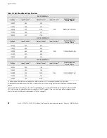
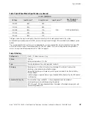
Page 34: ... displayed 5 If the system includes separate battery cabinets either EBMC or EBC record the ampere hour capacity of batteries installed in these cabinets If using an EBMC count the number of battery strings two battery modules side by side equals one string Each battery string contains 7 2 ampere hours If using an EBC refer to Table 3 for the total ampere hour value that corresponds to the type of...

Page 35: ...n be removed from operation before the alarm occurs This setting only affects the alarm the system continues to operate as an N X system even if this parameter is left at the default value of 0 Set Redundancy RSetting 0 ESC 7 To password protect the UPS On Off function press the Y or B button to make your selection then press the button If a password is required the UPS On and Off functions are ac...

Page 36: ...UPS Startup 30 Avayat RS9 UPS 9 18 kVA 9 Slot Models Site Preparation Installation and Operator s Manual S 164201543 Rev A ...

Page 37: ...ditions Double Conversion Line Conditioning Internal Bypass Battery Off Figure 18 UPS Operating Modes Under Auto Mode Control Double Conversion mode produces output power from the internal DC bus The AC input power is rectified and boosted to supply this DC bus The UPS switches automatically to and from Battery mode with no interruption 0 ms transfer time as AC input power drops and returns Batter...

Page 38: ...nd if the Auto Restart parameter is enabled switches to Double Conversion Auto Restart is enabled as a factory default After a discharge and subsequent low battery shutdown the UPS will automatically recover from Sleep mode if the Auto Restart parameter is enabled Figure 19 shows the basic functional elements of the UPS Input Utility Power Input Power Boost Converter Internal DC Power Bus DC AC Po...

Page 39: ...sconnected or turned off without first turning off the Avaya RS9 UPS If the input power source will be disconnected or turned off for more than a day or two you should put the UPS into Sleep mode Do this by turning the UPS off removing AC input power and then pressing the ON button and selecting Battery Protect BP Sleep mode allows the UPS to remain unpowered for up to six months without having to...

Page 40: ...oving into and out of display menus Also for avoiding a change to a parameter value and Y B Menu scroll up and down buttons Also for increasing decreasing parameter value digits Enter button to activate accept displayed parameter or operating mode Using the Front Panel Display The front panel display shows several important things see Figure 21 The numbers in the upper left corner for example 1 2 ...

Page 41: ... Top button B takes you to the top item in the current menu level in this case 1 2 1 And ESC button C enables you to move out of the current menu level in this case to menu 1 2 During normal operation the display appears as shown in Figure 22 Md indicates the current UPS operating mode and St indicates the operational state The number of power modules M and number of battery module strings B that ...

Page 42: ...ation Some useful parameters are input and output voltage input and output current and battery voltage The UPS measures or records many other parameters Some are operator adjustable such as the local date and time and various operating limits All parameters are password protected Although every operating condition and parameter is accessible through the front panel display you may change a value o...

Page 43: ...nformation can help in diagnosing power problems You can display the UPS Inverter and Alarm logs on the unit s front panel display these logs are in menu 2 Inverter Log The inverter Battery mode log is in menu 2 submenu 1 Move through the menu structure by pressing the Menu button and pressing the B button to move down to menu 2 Press to move to submenu 1 and press again to view the most recent en...

Page 44: ...switched to battery because the input voltage was too high or too low Battery Test Battery test initiated inverter operation Manual Operator initiated inverter operation Alarm Log The alarm log is in menu 2 submenu 2 Move through the menu structure by pressing the Menu button and pressing the B button to move down to menu 2 Press and press the B button to move down to submenu 2 The display shows t...

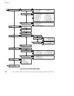
Page 45: ...pecific power or battery module slot number Slot XX appears in the upper right hand corner of the display as shown in Figure 25 indicating the slot number where the fault occurred See Troubleshooting on page 53 for detailed information on alarms 2 2 6 Slot 7 M 02 05 17 51 00 01 Open Cell Slot Top ESC Figure 25 Alarm Entry for Specific Slot Number Menu Map Figure 26 is an illustration of how to acc...

Page 46: ... ACIout P2 N 1 2 13 Full Load P1 1 2 6 VAOut 1 2 14 Full Load P2 1 2 7 VAout P1 N 1 2 15 PowerFactor L1 1 2 8 VAout P2 N 1 2 16 PowerFactor L2 1 3 1 Battery Volts 1 3 2 Run Time 1 3 3 Seconds on Battery ESC 4 3 1 Inv Relay Delay 4 3 2 EPO Mode 4 3 3 Ext Bypass Mode 5 1 Time 5 2 Date 5 3 Model Name 5 4 Serial Number 5 5 Software Version 1 1 Input Status 3 1 3 1 Test Interval 3 1 3 2 Test Time 1 2 O...

Page 47: ...Each Avaya RS9 UPS ships with LanSafe Power Management Software and an interface cable To begin installing LanSafe software see the instructions accompanying the Software Suite CD LanSafe software uses an RS 232 serial link to communicate with the UPS and it provides you with up to date graphics of UPS power and system data and power flow It also gives you a complete record of critical power event...

Page 48: ...otely with the Avaya RS9 system The Web SNMP Card also allows UPS dependent computer systems to automatically shut down during extended power outages using the NetWatch client software provided on the Software Suite CD Optional Relay Card The relay card provides true relay contact output to peripheral devices Outputs are user selectable as normally open or normally closed Refer the instructions in...

Page 49: ...S Phase Lock Window and Frequency Slew Rate These parameters increase the rate at which the UPS tracks the input line which causes fewer recognized line faults during generator instability S Frequency Glitch Count This parameter increases the number of bad frequency cycles before the unit transfers to battery power This allows the UPS to operate smoothly during generator instability without transf...

Page 50: ...l Vdc for at least 5 seconds but not more than 7 seconds during an AC Failure condition the UPS output shuts off following a delay of 120 seconds 5 seconds S The UPS output shuts off even if the normal AC input power is restored during the 120 second delay S The UPS output automatically restarts after the UPS determines the normal AC input power is stable S The shutdown and restart timing represen...

Page 51: ...erals Nevertheless the Avaya RS9 UPS and optional battery cabinets do require some attention to assure continued reliable service The service technician should follow the recommended maintenance schedule which includes the following items S Check operating environment for clean cool dry conditions S Inspect and clean the unit S Check operation of fans power modules S Check and tighten all connecti...

Page 52: ...n Extended Battery Cabinet is used If an EBC is used only one internal battery string is required The UPS may indicate an alarm with no batteries present Use the following procedure to replace battery modules in pairs 1 Remove the front cover panel s from the battery modules you need to replace The panels have spring latches on the left and right sides that hold them in place 2 Grasp the battery m...

Page 53: ...supply the required power If empty slots exist install replacement modules before removing original ones Use care in removing and installing power modules or battery charger modules To remove a power module 1 Remove the front cover panel The panels have spring latches on the left and right sides that hold them in place 2 Loosen the thumbscrew on the module handle Press down on the latch release at...

Page 54: ...carefully into the cabinet Lower the front down slightly and lift the rear edge over the safety stop on the center support rail Keep the module handle extended until the module is fully inserted 6 Raise the module handle to secure the module into the cabinet Be sure the handle latch snaps into place Tighten the thumbscrew on the handle 7 Reinstall the front cover panel ...

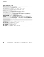
Page 55: ...tput frequency tracks input frequency to selectable limit 0 1 to 5 0 Hz 3 0 Hz default switches to battery operation outside this tolerance On battery 60 Hz 0 1 Hz Regulation 3 load regulation under any line load or battery condition Voltage Waveform Sine wave 3 THD at rated linear loads computer grade power Overload Capability 150 for 10 seconds 300 for 12 cycles DC Input Protection DC fuse and b...

Page 56: ...A 120 240 56A 50A 15 kVA 12500 Watts Voltage Input Current Output Current Input Service Heat Dissipation Normal Mode 100 200 80A 75A 110 220 75A 70A 120 208 70A 72 5A 100A 1430W 4 88 kBTU hr 127 220 65A 70A 120 240 70A 62 5A In Bypass modes the input current equals the output current plus 2A for each power module in the system For redundant power module operation N X increase the input current rat...

Page 57: ... support the maximum capacity of the UPS cabinet If you are installing a battery charger module refer to the input circuit breaker requirements in Table 1 on page 12 Table 10 Battery Configuration 2 60V 7 2 Ah batteries per string Voltage 120 Vdc Battery charger module 133 Vdc Type Sealed maintenance free valve regulated lead acid Charging Recharge time 4 hr after full load resistive discharge 8 h...

Page 58: ... operating ambient temperature decreases 1 C per 300m above 1525m 2 F per 1000 ft above 5000 ft Non Operating Altitude Up to 12 200 meters above sea level 40 000 ft Ventilation The air around the UPS must be clean and free of dust corrosive chemicals and other contaminants The Avaya RS9 UPS uses internal fans to circulate the air for cooling The air must be free to circulate around the UPS and bat...

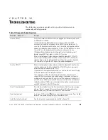
Page 59: ...s the green LED illuminates to signal the UPS is operating and producing power Turn the UPS off Refer to the front panel display and press the button labeled OFF Confirm the selection by pressing the button labeled Yes If On Off control is password protected enter the user password 0377 In the event of a front panel display failure you can turn the unit on or off using a computer connected to the ...

Page 60: ...about making this or other password protected adjustments contact your Avaya service representative Change the level of system redundancy To view or change the redundancy level go to menu 4 2 5 Change the batteries Each side by side pair of battery modules forms one series string on the battery bus See Battery Replacement on page 46 for the battery replacement procedure Add delete one or more stri...

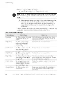
Page 61: ...of the display to help identify the cause of the alarm The third line may also display a specific slot number where the fault occurred If the alarm is not specific to a slot number System appears on the display M Batt Test Failed 1 Open Cell Slot 4 A B C Silence Clear ESC Figure 29 Detailed Alarm Entry When the Avaya RS9 UPS detects an alarm condition the UPS displays the alarm with the following ...

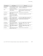
Page 62: ...en AC input power returns the UPS begins recharging batteries and applies power to the load C High Battery The battery voltage is too high because of a charger problem battery problem or incorrect parameter setting Contact your Avaya service representative E Low AC Output The UPS has shut down because the AC output voltage is too low to provide power to the load Contact your Avaya service represen...

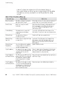
Page 63: ...ct the input wiring problem and restart the UPS T Call Service Module Failure A power module has detected an internal fault and has shut down Look for the slot number third line on display of the power module and replace the defective module T Call Service Excessive Transfers The UPS has detected an excessively high number of automatic transfers and has switched to Double Conversion Auto mode Cont...

Page 64: ...stem test Contact your Avaya service representative M Check Battery Open Cell A battery pair of modules has failed an open cell test Look for the slot number third line on display of the failed modules Verify that both battery modules are properly installed If properly installed replace both battery modules M Check Battery Weak Battery The system batteries have degraded to the point where system r...

Page 65: ... Item Material Code Description 9 Slot UPS Enclosure 700326689 RS9 UPS Chassis 9 Slot Enclosure Hardwired In Out 9 Slot EBMC 700326705 RS9 UPS Battery Chassis 9 Slot Enclosure SNMP Web Adapter 700249048 RS9 ConnectUPSt Web SNMP Card 3 kVA Power Module 700248974 RS9 3 kVA UPS Power Module Battery Module 700248982 RS9 Internal Battery Module 20A Charger Module 700249030 RS9 Internal 20A Battery Char...

Page 66: ...Troubleshooting 60 Avayat RS9 UPS 9 18 kVA 9 Slot Models Site Preparation Installation and Operator s Manual S 164201543 Rev A ...

Page 67: ......

Page 68: ...164201543 A 164201543A ...

Reviews: