Operation
35
Avaya
t
RS9 UPS (9–18 kVA, 9-Slot Models) Site Preparation, Installation and Operator’s Manual
S
164201543 Rev A
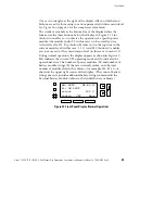
One or two triangles at the right of the display tells you which arrow
buttons are active for moving to various parameters within a menu level.
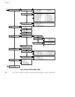
See Figure 26 on page 40 for the complete system menu.
The words or symbols in the bottom line of the display define the
function of the three buttons below the display. In Figure 21, Slot
(button A) enables you to observe the operation of a specific power
module (the module in slot #2, in this case) or the overall system
(selected as slot #0). Top (button B) takes you to the top item in the
current menu level (in this case, 1 2 1). And ESC (button C) enables
you to move out of the current menu level (in this case, to menu 1 2).
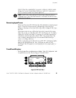
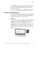
During normal operation, the display appears as shown in Figure 22.
Md: indicates the current UPS operating mode and St: indicates the
operational state. The number of power modules (M) and number of
battery module strings (B) that are currently online, and the total
number of module slots in the cabinet—for example, M4-B7-12—is
shown in the upper right corner of the display. (The count of battery
strings does not include additional battery strings contained in the
External Battery Module Cabinet or Extended Battery Cabinets.)
Md: AUTO
M4-B7-12
St: ON LINE
acvout
232 V
Config
OFF
Menu
Figure 22. Front Panel Display (Normal Operation)


