


Caution:
Avaya strongly recommends that system configuration changes be made only by qualified
service personnel. If necessary, consult with Avaya technical support or field service
engineering.
Verify the new assemblies in the following order.
1. Verify or modify the boot ROM settings for the new DCC. See Verifying and Modifying Boot
ROM Settings.
2. Then verify and modify the boot ROM for the new TMS. See
on page 126.
3. Repeat the preceding two steps for each new TMS in the system.
Checking the boot ROM is an interactive process. If you elect to modify any of the current boot ROM
settings, you are prompted on each individual item to change or accept the current value (press
<RETURN>).
DCC Boot ROM
Perform the following procedure for each DCC in the TMS to verify and modify the boot ROM
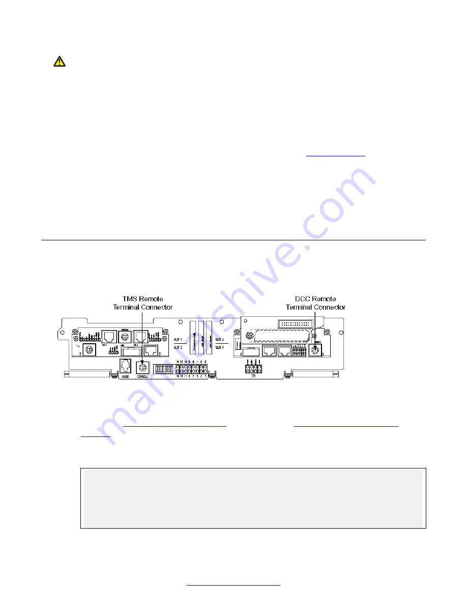
settings. Refer to the following TMS front panel diagram for connector locations.
Figure 35: TMS Front Panel
1. Connect a serial console to the remote terminal connector of the DCC. (See preceding
on page 124 and
on page 134.)
2. Cycle the power on the TMS. The ROM banner and the current settings appear on the serial
console. Press any key within 5 seconds to suspend the system boot.
DCC-3000 Rom $Revision: 1.8 $, Checksum = 0x192740c9
dcc3k_rom.elf, Release ROM-5.0 [05/06/05 05:31:50 PM]
Copyright (C) 2013, Avaya Inc. All rights reserved
--------------------------------------------------------------------------
START-UP MODE:
Run the ROM Bootloader
HOST DEBUGGER CONNECTION (if activated):
Network connection
Configuration (Part II)
124
Avaya Media Processing Server 500 Hardware Installation and Maintenance
October 2014