16
Avago Technologies Confidential
Low Speed Logic
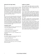
Management signaling logic levels are based on Low Voltage CMOS operating at 3.3 V V
cc
. Host shall use a pull-up
(1.5 kohm – 10 kohm) to V
cc3.3
for the Two-wire interface SCL (clock), SDA (address & data), and Int_L/Reset_L signals.
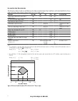
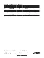
Low Speed Control and Sense Signal Specifications
Parameter
Symbol
Min
Max
Units
Condition
Module Input Voltage Low
V
il
-0.3
0.4
V
Pull-up to 3.3V.
Min Vih = 0.7*3.3V.
Module Input Voltage High
V
ih
2.3
3.6
V
Module Output Voltage Low
V
ol
-0.3
0.3
V
Condition I
OL
=3.0 mA. Pull-up to 3.3V.
Module Output Voltage High
V
oh
2.8
3.6
V
Min Voh = 3.3V - 0.5V.
Module Output Current High
I
oh
-10
10
m
A
-0.3 V < Voutput < 3.6 V
Capacitance of module on SCL, SDA
and Int_L/Reset_L I/O contacts
C
i,SCLSDA
36
pF
Allocate 28 pF for IC, 8 pF for module PCB
Capacitance of module on
Int_L/Reset_L I/O contact
C
i,INT_L
36
pF
Allocate 28 pF for IC, 8 pF for module PCB
Total bus capacitive load, SCL, SDA
and Int_L/Reset_L I/O pin
C
b
100
pF
3.0 k
W
Pullup resistor, max
200
pF
1.6 k
W
Pullup resistor, max
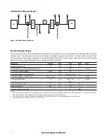
Management Interface Timing Specification
Figure 7. Two-wire Serial Interface Timing Diagram
SCL
SDA
STOP
ReSTART
START
t
SU,STO
t
F
t
t
F
t
R
t
HIGH
t
HD,DAT
t
SU,DAT
t
R
t
SU,STA
t
HD,STA
t
LOW


