9
Avago Technologies Confidential
Receiver Optical Characteristics
The following characteristics are defined over the Recommended Operating Conditions unless otherwise noted. Typical
values are for Tc = 40°C, Vcc33 = 3.3 V
Parameter
Test Point
Min
Typ
Max
Units
Notes/Conditions
Center wavelength, each lane
TP3
840
850
860
nm
Damage Threshold
TP3
3.4
dBm
Note 1
Average power at receiver input, each lane
TP3
-9.5
2.4
dBm
Receiver Reflectance
TP3
-12
dB
Optical Modulation Amplitude (OMA),
each lane
TP3
-7.5
3
dBm
Stressed receiver sensitivity in OMA,
each lane
TP3
-5.4
dBm
Measured with confor-
mance test signal at TP3
for BER = 10e-12
Peak power, each lane
TP3
4
dBm
Conditions of stressed receiver sensitivity:
TP3
Note 2
Vertical Eye Closure Penalty, each lane
TP3
3.5
dB
Stressed eye J2, Jitter, each lane
TP3
0.30
UI
Stressed eye J9, Jitter, each lane
TP3
0.47
UI
OMA of each aggressor lane
TP3
-0.4
dBm
Rx LOS Assert Threshold
TP3
-30
dBm OMA
Rx LOS De-assert Threshold
TP3
-8
dBm OMA
LOS Hysteresis
TP3
0.5
dB
Notes:
1. The receiver shall be able to tolerate, without damage, continuous exposure to a modulated optical input signal having this power level on one
lane. The receiver does not have to operate correctly at this input power
2. Vertical eye closure penalty and stressed eye jitter are test conditions for measuring stressed receiver sensitivity. They are not characteristics of the
receiver. The apparent discrepancy between VECP and TDP is because VECP is defined at eye center while TDP is defined with ±0.15 UI offsets of
the sampling instant
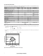
Figure 5. Required characteristics of the conformance test signal at TP3 – definitions of the conditions of stressed receiver sensitivity
A
0
OMA
J
P
1
P
0
Vertical eye closure histograms
(at time-center of eye)
Approximate OMA (difference of
means of histograms)
Jitter histogram (at waveform
average, may not be at waist)


