4
Avago Technologies Confidential
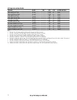
Absolute Maximum Ratings
Stress in excess of any of the individual Absolute Maximum Ratings can cause immediate catastrophic damage to the
module even if all other parameters are within Recommended Operation Conditions. It should not be assumed that
limiting values of more than one parameter can be applied to the module concurrently. Exposure to any of the Absolute
Maximum Ratings for extended periods can adversely affect reliability.
Parameter
Symbol
Min
Max
Units
Notes
Storage Temperature
Ts
-40
85
°C
Absolute Maximum Operating Temperature
85
°C
Note 1
3.3 V Power Supply Voltage
Vcc33
-0.5
4.0
V
Data Input Voltage – Single Ended
-0.5
Vcc33+0.5, 4.0
V
Data Input Voltage – Differential
|V
dip
- V
din
|
1.6
V
Note 2
Control Input Voltage
Vi
-0.5
Vcc33+0.5
4.0
V
Note 3
Control Output Current
Io
-20
20
mA
Relative Humidity
RH
5
85
%
Receiver Damage Threshold
4
dBm
Notes:
1. Electro-optical specifications are not guaranteed outside the recommended operating temperature range. Operation at or above the maximum
Absolute Maximum Case Temperature for extended periods may adversely affect reliability.
2. This is the maximum voltage that can be applied across the differential inputs without damaging the input circuitry.
3. The maximum limit is the lesser of Vcc33 + 0.5 V or 4.0 V
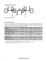
Link Model and Reference Channel
Figure 1. Link Model test point definitions
Optical Patch Cord
Electrical Connector
TP1
TP0
TP1a
TP4a TP4
TP5
TP2
TP3
Electrical Connector
ASIC
ASIC
CXP TX
CXP RX


