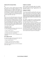
7
Avago Technologies Confidential
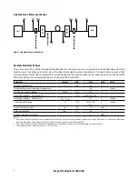
Receiver Electrical Characteristics
The following characteristics are defined over the Recommended Operating Conditions, with module default settings,
unless otherwise noted. Typical values are for Tc = 40°C, Vcc33 = 3.3 V
Parameter
Test Point
Min
Typ
Max
Units
Notes/Conditions
Data Output Differential Peak-to-Peak
Voltage Swing
TP4
220
850
mV
AC common mode voltage (RMS)
TP4
7.5
mV
RMS
Termination mismatch at 1MHz
TP4
5
%
Differential output return loss
TP4
footnote
10 MHz to 11.1 GHz
Note 1
Common-mode output return loss
TP4
footnote
10 MHz to 11.1 GHz
Note 2
Output transition time 20% to 80%
TP4
28
ps
TJ Jitter output
TP4
0.75
UI
DJ Jitter output
TP4
0.45
UI
RJ Jitter output
TP4
0.30
UI
Data Dependent Pulse Width Shrinkage
(DDPWS)
TP4
0.34
UI
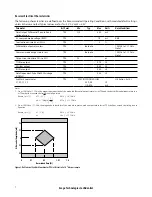
Eye Mask coordinates:
X1, X2, Y1, Y2
TP4
SPECIFICATION VALUES
0.29, 0.5
110, 425
UI
mV
Hit Ratio = 5x10
-5
Notes:
1. From 10 MHz to 11.1 GHz, the magnitude in decibels of the module differential output return loss at TP4 and the host differential input return loss
at TP4a shall not exceed the limit given in Equation
2. From 10 MHz to 11.1 GHz, the magnitude in decibels of the module common-mode output return loss at TP4 shall not exceed the limit given in
Equation
Return_loss (
ƒ
)
≥ 7 – 1.6
ƒ
0.01 ≤
ƒ
< 2.5 GHz
≥ 3
2.5 ≤
ƒ
< 11.1 GHz
Return_loss (
ƒ
)
≥ 12 – 2√
ƒ
0.01 ≤
ƒ
< 4.1 GHz
≥ 6.3 – 13log
10
4.11 ≤
ƒ
< 11.1 GHz
ƒ
5.5
Figure 3. Rx Electrical Eye Mask Coordinates (TP4) at Hit ratio 5 x 10
-5
hits per sample
Differential Amplitude [mV]
Normalized Time [UI]
0
X1
X2
1-X1
1.0
Y2
-Y2
Y1
-Y1
0


