8
Avago Technologies Confidential
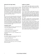
Figure 4. Transmitter eye mask definitions (TP2) at Hit ratio 5 x 10
-5
hits per sample
Normalizd Amplitude
1-Y2
Y2
0.5
1-Y1
Y1
1+Y3
-Y3
Normalized Time (Unit Interval
0
X1
X2
1-X2
1-X1
1.0
X3 1-X3
1
0
Mask Coordinates
X1 = 0.23
X2 = 0.34
X3 = 0.43
Y1 = 0.27
Y2 = 0.35
Y3 = 0.40
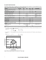
Transmitter Optical Characteristics
The following characteristics are defined over the Recommended Operating Conditions unless otherwise noted. Typical
values are for Tc = 40°C, Vcc33 = 3.3 V
Parameter
Test Point
Min
Typ
Max
Units
Notes/Conditions
Center wavelength
TP2
840
850
860
nm
RMS spectral width
TP2
0.65
nm
RMS Spectral Width is the
standard deviation of the
spectrum
Average launch power, each lane
TP2
-7.6
2.4
dBm
Optical Modulation Amplitude (OMA)
each lane
TP2
-5.6
3
dBm
Even if the TDP<0.9 dB,
the OMA minimum must
exceed this minimum value
Difference in launch power between
any two lanes (OMA)
TP2
4
dB
Peak power, each lane
TP2
4
dBm
Launch power in OMA minus TDP,
each lane
TP2
-6.5
dBm
Transmitter and dispersion penalty (TDP),
each lane
TP2
3.5
dB
Extinction ratio
TP2
3
dB
Optical return loss tolerance
TP2
12
dB
Encircled flux
TP2
≥ 86% at 19
m
m,
≤ 30% at 4.5
m
m
If measured into type A1a.2
50
m
m fiber in accordance
with EN 61280-1-4
Eye Mask coordinates:
X1, X2, X3, Y1, Y2, Y3
TP2
SPECIFICATION VALUES
0.23, 0.34, 0.43, 0.27, 0.35, 0.4
UI
Hit Ratio = 5x10
-5
Average launch power of OFF transmitter,
each lane
TP2
-30
dBm


