5
Avago Technologies Confidential
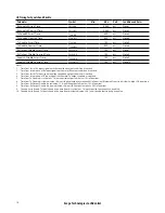
Recommended Operating Conditions
Recommended Operating Conditions specify parameters for which the electrical characteristics hold unless otherwise
noted. Electrical characteristics are not defined for operation outside the Recommended Operating Conditions, reliabil-
ity is not implied and damage to the module may occur for such operation over an extended period of time.
Parameter
Symbol
Min
Typ
Max
Units
Notes
Case Temperature
Tc
0
70
°C
3.3 V Power Supply Voltage
Vcc33
3.135
3.3
3.465
V
Signal Rate per Channel
12.5
GBd
Note 1
Control Input Voltage High
Vih
2.3
3.6
V
Control Input Voltage Low
Vil
-0.3
0.4
V
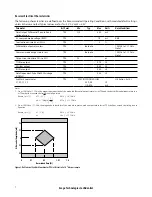
Host Electrical Compliance
TJ Jitter output (TP1a)
DJ Jitter output (TP1a)
RJ Jitter output (TP1a)
TJ Jitter tolerance (TP4)
DJ Jitter tolerance (TP4)
RJ Jitter tolerance (TP4)
0.75
0.45
0.30
0.25
0.15
0.10
UI
UI
UI
UI
UI
UI
Note 2
Fiber Length: 4700 MHz•km 50
m
m MMF (OM4)
65
m
Note 3
Fiber Length: 2000 MHz•km 50
m
m MMF (OM3)
50
m
Receiver Differential Data Output Load
100
W
Note:
1. For applications other than 12.5 Gbps per channel, please contact Avago Sales.
2. Per IEEE 802.3ba-2010 TP1a and TP4 CPPI specifications for host except for jitter.
3. 1.5dB allocated for connection and splice loss.
Transceiver Electrical Characteristics
The following characteristics are defined over the Recommended Operating Conditions unless otherwise noted. Typical
values are for Tc = 40°C, Vcc33 = 3.3 V
Parameter
Symbol
Min
Typ
Max
Units
Notes
Transceiver Power Consumption
3.5
W
With module
default settings
Transceiver Power Supply Current – Vcc33
1.1
A
With module
default settings
Maximum inrush current
1.25
A
On any contact
Maximum current ramp rate
100
mA/
m
s
Power Supply Noise including ripple
50
mVpp
Note 1
Power On Initialization Time
t
pwr init
2000
ms
Two Wire Serial Interface Clock Rate
400
kHz
TWS Write Cycle Time (4 byte write)
40
ms
Note:
1. 1 kHz to frequency of operation at the host supply side of the recommended power supply filter with the module and recommended filter in place.
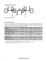
See Figure 9 for recommended power supply filter.


