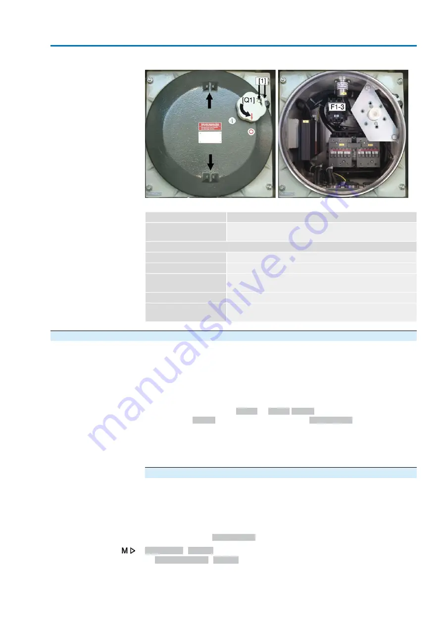
Figure 93: Control box
Table 37:
Description
Fuses
Isolating switch (3-pole)
Size/type: 10 x 38 mm aM 16 A, slow-blow, 500 V
F1–3
Further compontents
Contactors
K2.1/K1.1
Disconnect switch (3-pole)
Q1
Heaters for control box, 100 W each
R6.1 H (option)
R6.2 H (option)
Heater for flameproof enclosure, 100 W
R7 H (option)
Thermostat for heaters within the control box 14 °C/4 °C
Thermostat for heater within the flameproof enclosure 14 °C/4 °C
TR1 (Option)
TR2 (Option)
11.3.4.
Motor protection (thermal monitoring)
In order to protect against overheating and impermissibly high surface temperatures
at the actuator, PTC thermistors or thermoswitches are embedded in the motor
winding. Motor protection trips as soon as the max. permissible winding temperature
has been reached.
The actuator is switched off and the following signals are given:
●
LED 3 (motor protection trippped) on the local controls is illuminated.
●
The status indications
S0007
or
S0011 Failure
display a fault.
The fault
Details
is displayed when selecting
Thermal fault
.
The motor has to cool down before operation can be resumed.
Depending on the parameter setting (motor protection behaviour), the fault signal is
either automatically reset or the the fault signal has to be reset using RESET push
button with selector switch position Local operation (LOCAL).
Proof-test motor protection
Test correct functioning of the motor protection as described hereafter. Perform the
functional test at the latest within the framework of maintenance (refer to chapter
<Servicing and maintenance>).
The test is performed by simulating the motor protection signal via actuator controls
local controls:
Required user level:
Specialist (4)
or higher.
Diagnostic M0022
TMS proof test M1950
Test procedure:
1.
Set selector switch to position 0 (OFF).
83
SAEx 25.1 – SAEx 40.1 / SAREx 25.1 – SAREx 30.1
ACExC 01.2
Corrective action


