


LED DISPLAY
ChromaFlex Chassis – Operation Manual
2-1
ATX Confidential & Proprietary
LED DISPLAY
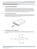
2. LED Display
The chassis has a single status LED on the controller module and each plug-in application module has module specific
LEDs that are visible from the front panel. The LED trigger conditions shall be included in each individual module chapters.
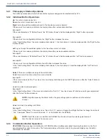
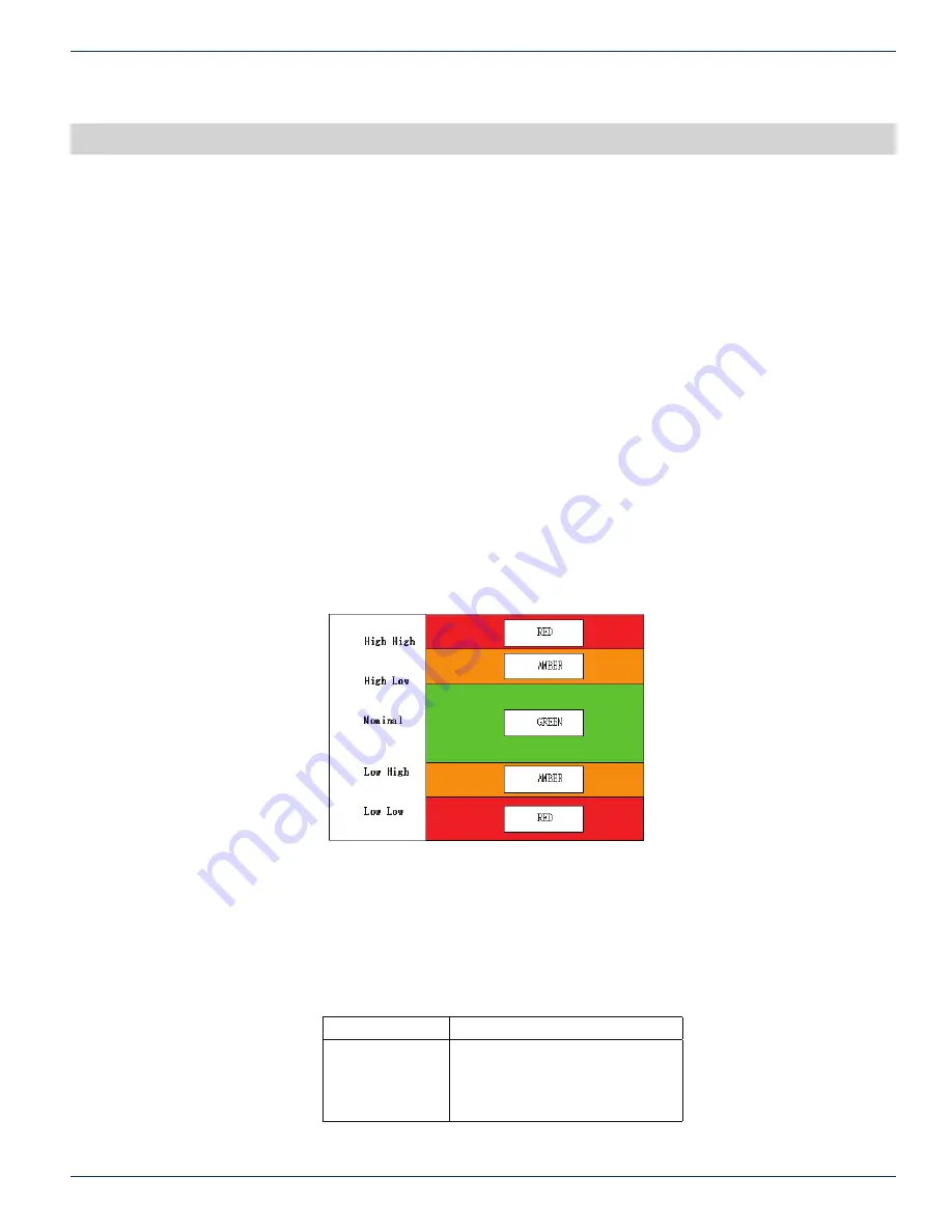
2.1 LED Color Codes
There are four possible colors of LEDs. They are observed during the following conditions.
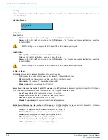
Off:
indicates the monitored function is unavailable. This is also observed temporarily during power on LED test.
Green:
indicates the monitored function is healthy. This is also temporarily observed during power on LED test.
Amber: indicates the monitored function is in minor alarm condition. This is also temporarily observed during power on LED
test.
Red:
indicates the monitored function is in major alarm condition. This is also observed temporarily during power on LED
test.
Power up LED test:
At the beginning of each power up of all modules, the color of all LEDs turns from Red, Yellow to Green.
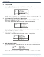
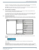
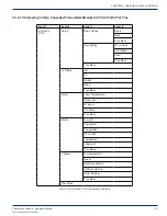
Figure 1: Generic Alarm & LED Table
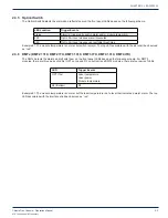
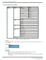
2.2 Chassis Controller
The chassis controller module contains the system software and provides the user access to provision and monitor the
chassis and plug-in application modules. The controller is responsible for reporting the chassis and plug-in module related
status and alarm conditions. The chassis related alarms are reflected on the controller module front panel Status LED.
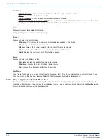
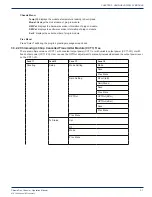
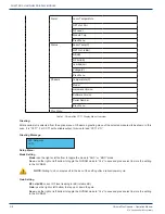
LED
Trigger Events
Status
Power supply
Fan
Module temperature
CHAPTER 2:


