HAND-HELD DISPLAY MODULE
ChromaFlex Chassis – Operation Manual
3-17
ATX Confi dential & Proprietary
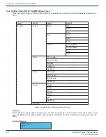
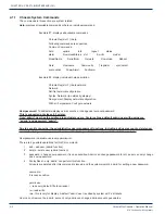
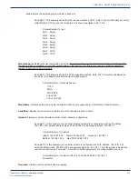
Greeting:
After a valid slot is selected from the option menu of Chassis, a greeting menu of the selected module will be shown; in this
case, it is “DMTX”. The modules covered under DMTX includes, DMT3 1310, DMT3 ITU, DMT4 1310, DMT4 ITU.
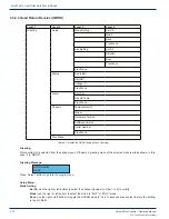
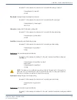
Greeting Message:
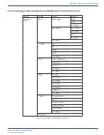
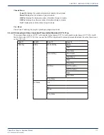
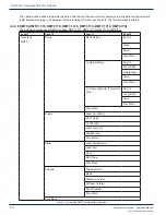
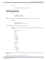
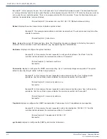
Setup Menu:
Mode Setting
Sel_Ch:
use the right or left bottom to select the channel (number 1 to 4 for DMT4 or 1 to 3 for DMT3) to modify..
Mode:
use the right or left bottom to toggle the mode to “AGC” or “MGC” mode.
Save:
use the right or left bottom to toggle the NVRAM mode to “Yes” to save and press select to store the setting
in the NV RAM.
NOTE: Failing to do so may result in the loss of the setting after a reboot/power cycle.
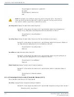
Tx Gain Setting
Sel_Ch:
use the right or left bottom to select the channel (number 1 to 4 for DMT4 or 1 to 3 for DMT3) to modify.
RF Lvl(dB):
current RF level reading in dB.
Gain(steps):
use the right or left bottom to step up or down the gain.
Save:
use the right or left bottom to toggle the NVRAM mode to “Yes” to save and press select to store the setting
in the NV RAM.
NOTE: Failing to do so may result in the loss of the setting after a reboot/power cycle.
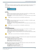
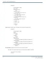
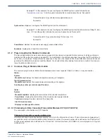
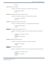
Tx Fiber Length
This option is for ITU version only
Sel_Ch:
use the right or left bottom to select the channel (number 1 to 4 for DMT4 or 1 to 3 for DMT3) to modify.
Length:
use the right or left bottom to step up or down the length.
The factory default setting for this fi eld is 10 km with adjustable range of 0-50km at 1 km increment.
Save:
use the right or left bottom to toggle the NVRAM mode to “Yes” to save and press select to store the setting
in the NV RAM.
NOTE: Failing to do so may result in the loss of the setting after a reboot/power cycle.
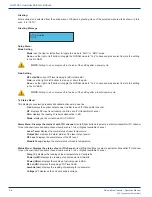
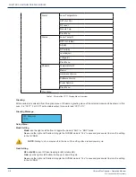
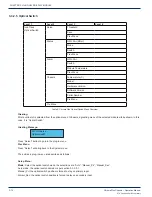
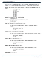
Alarm Menu:
Displays the alarm state of each channel. Use left/right buttons to select a particular channel display. Available
channel numbers are 1 to 4 for DMT4 or 1 to 3 for DMT3.
Laser Temp:
displays the alarm status of laser temperature.
Laser Pwr
: displays the alarm status of the laser output power.
RF Level
: displays the alarm status of the RF level.
Mod Temp:
displays the alarm status of module temperature.
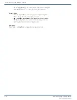
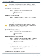
Status Menu:
Displays the reading of each channel. Use left/right buttons to select a particular channel display. Available
channel numbers are 1 to 4 for DMT4 or 1 to 3 for DMT3.
Laser Pwr (dBm):
displays the reading of optical power in dBm.
RF Lvl (dB)
: displays the reading of RF level in dB.
Tx Attn (dB)
: displays the transmitter attenuation reading in dB.
ATX Networks
DMTX
CHAPTER 3:


