


Connecting via Optical Fiber
1
Connect the Blackmagic Camera’s optical out/in to the optical out/in on an ATEM
Studio Converter or Talkback Converter 4K. You’ll need to have SMPTE compatible
optical fiber SFP modules installed in your Studio Camera and ATEM converter to
connect via optical fiber.
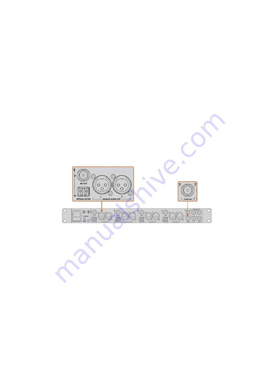
2
Connect a suitable SDI out from your ATEM converter to any SDI input on your
ATEM switcher.
3
Connect any one of your ATEM switcher’s SDI outputs, except down converted or multi
view outputs to your ATEM Converter’s ‘SDI in’. Camera control signals are not sent via
the multi view and down converted SDI outputs.
4
On the Blackmagic camera, open the LCD menu and set the camera number to to
match your switcher input. For example, if studio camera 1 is connected to ‘cam 1’ on
your ATEM switcher, your camera number must also be set to 1. This ensures tally is
sent to the correct camera.
Open ATEM Software Control preferences and set your switcher’s button mapping to make sure
you are switching the right camera with correct tally. With a video connection from your switcher
to a Blackmagic camera, you can also get the advantage of live tally indicators, as well as the
camera operators being able to view the program feed of your switcher by pressing the
camera’s ‘pgm’ button.
Connect multiple Blackmagic Studio Cameras via optical fiber using an ATEM Studio Converter. You’ll
need to have an optional SFP module installed in your Studio Camera to connect via optical fiber.
Camera Control Panel
Launch ATEM Software Control and click on the ‘camera’ button located at the bottom of the
software window. You’ll see a row of labeled Blackmagic camera controllers containing tools to
adjust and refine each camera’s image. The controllers are easy to use. Simply click the buttons
using your mouse, or click and drag to adjust.
Camera Control Selection
The button row at the top of the camera control page lets you select the camera number you
would like to control. If you have more cameras that fit onto the window size, or you are running
the color corrector window, then you can use these buttons to select between which camera
you would like to control. If you are using an Aux output for monitoring your camera control,
pushing these buttons to change the camera to control will also send that camera’s video
output to the Aux output setup in the switcher preferences.
Channel Status
The channel status at the top of each camera controller displays the camera label, On Air
indicator and lock button. Press the lock button to lock all the controls for a specific camera.
When on air, the channel status illuminates red and displays the On Air alert.
76
Using Camera Control