Directional Control Valve
Removal
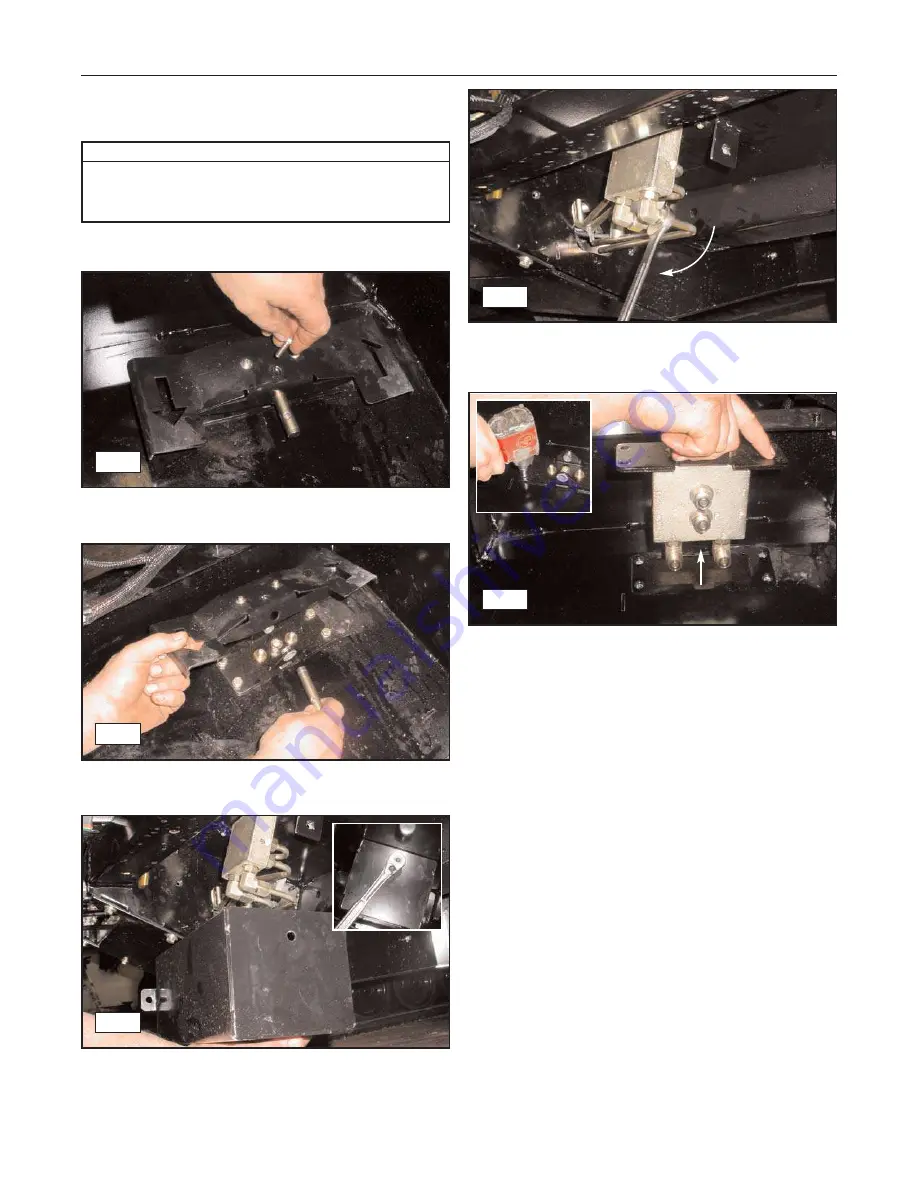
1.
Relax any hydraulic actuators to relieve pressure
within the hydraulic system.
2.
Remove the bolts securing the foot pedal pivot pin
in place. (fig. 10-41)
3.
Slide the pin out of the assembly and remove the
foot pedal from the machine. (fig. 10-42)
4.
Remove the bolts securing the control valve cover
to the chassis. (fig. 10-43)
5.
Disconnect the tubes from the control valve as
shown. Cap and plug tubes and fittings to prevent
fluid loss or contamination. (fig. 10-44)
6.
Remove the bolts securing the valve to the floor of
the cab as shown, then lift the valve upward and
remove. (fig. 10-45)
Installation
1.
To install the directional control valve, reverse the
removal procedure.
10-10
Rubber Track Utility Vehicle
10. Hydraulic Components
Required Tools
Combination/Socket Wrenches
Hydraulic Caps/Plugs
Allen Wrenches (t-handle)
10-41
10-42
10-43
10-44
10-45
https://tractormanualz.com/
Summary of Contents for SC50 Scout
Page 9: ...Intentionally left blank https tractormanualz com ...
Page 11: ...Intentionally left blank https tractormanualz com ...
Page 21: ...Intentionally left blank https tractormanualz com ...
Page 45: ...Intentionally left blank https tractormanualz com ...
Page 57: ...Intentionally left blank https tractormanualz com ...
Page 61: ...Intentionally left blank https tractormanualz com ...
Page 79: ...Intentionally left blank https tractormanualz com ...
Page 99: ...Intentionally left blank https tractormanualz com ...
Page 105: ...Intentionally left blank https tractormanualz com ...
Page 109: ...Intentionally left blank https tractormanualz com ...


