159
STRIP BLADE CALIBRATION
This is a mechanical calibration so that the lead and tail strip blades close to the same diameter. The reason that
this calibration may be necessary is because the blade holders may not be perfectly perpendicular to each other
or the blades are slightly different lengths.
Before starting this procedure make sure the strip blades are all fully seated in the tool holders.
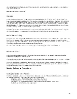
To adjust the length of the strip blade so that the strip diameter is exactly the same on the lead and tail side.
‐
Measure both the lead and the tail strip blade opening or use something like a small rod to gauge the
opening.
‐
Loosen the upper blade holder on the strip blade opening you would like to adjust.
‐
Turn the adjustment screw clockwise to make the opening smaller, counter clockwise to make the
opening larger. Make sure to push the bald and holder up against the stop to get an accurate reading.
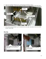
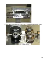
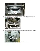
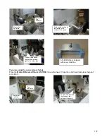
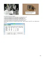
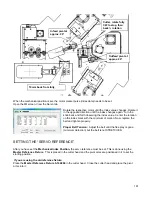
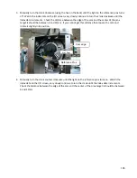
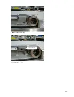
The adjustment set screws are on both the top and the bottom tool holders as shown on the picture
below.
REFERENCE POSITIONS
MOTOR AND BELT REPLACEMENT
Drive Belt Replacement
When replacing the belts on the
CR
they should be pulled tight but not preloaded or stretched. Anytime a belt is
replaced a Master Reference must be performed. See the following section.
When replacing belts, the relationship between the reference position and the marker pulse on the subject motor
encoder must be set. Each axis has a mechanical position at which the pulse should increment. (This does not
Strip blade length
set screw
Strip blade length
set screw

