


Functional Description
MVME8100 / MVME8110 Installation and Use (6806800P25J
)
96
4.13 PMC/XMC Sites
The MVME8100 / MVME8110 provides two PMC/XMC sites. Each PMC/XMC site will accept
either a PMC or an XMC add-on card. For a given PMC/XMC site, only an XMC or a PMC maybe
populated at any given time, as they occupy the same physical space on the PCB. The
PMC/XMC1 site provides rear PMC I/O.
The PMC/XMC sites are fully compliant with the following:
VITA 39 -PCI-X for PMC
VITA 35-2000 for PMC P4 to VME P2 Connection (PMC/XMC1 site only)
PCI Rev 2.2 for PCI Local Bus Specification
PCI-X PT 2.0 for PCI-X Protocol Addendum to the PCI Local Bus Specs
IEEE Standard P1386-2001 for Standard for Common Mezzanine Card Family
IEEE Standard P1386.1-2001 for Standard Physical and Environmental Layer for PCI
Mezzanine Card.
VITA 42 for XMC
VITA 42.3, PCIe for XMC
PMC/XMC sites are keyed for 3.3V PMC signaling.
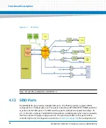
MVME8100 / MVME8110 provides a x8 PCI Express interface link for PMC/XMC1 and x4 PCI
Express interface link for PMC/XMC2. It is designed such that same PCI Express interface is used
for either the XMC or the PCIe to PCI-X bridge required for a PMC. This is made possible by using
Pericom PI3PCIE3412 PCIe mux devices. The PCIe Mux at both sites is controlled by the CPLD.
The CPLD detects the presence signal provided by the XMC or PMC board and it will be used to
configure the routing of PCIe Mux accordingly.
4.13.1 PMC Add-on Card
The MVME8100 / MVME8110 supports up to two PMC cards. PCI-X operation to each site is
provided using a separate IDT TSI384 PCIe to PCI-X bridge for each site. Each Tsi384 can
support up to 8.5Gbps (64bits x 133 Mhz). An onboard switch will configure the TSI384 to run
on either 100 MHz or 133 MHz. The default is 133 MHz.
Summary of Contents for MVME8100
Page 1: ...MVME8100 MVME8110 Installation and Use P N 6806800P25J August 2015 ...
Page 8: ...MVME8100 MVME8110 Installation and Use 6806800P25J 8 List of Tables ...
Page 10: ...MVME8100 MVME8110 Installation and Use 6806800P25J 10 List of Figures ...
Page 26: ...MVME8100 MVME8110 Installation and Use 6806800P25J Sicherheitshinweise 26 ...
Page 58: ...Hardware Preparation and Installation MVME8100 MVME8110 Installation and Use 6806800P25J 58 ...
Page 84: ...Connectors LEDs and Switches MVME8100 MVME8110 Installation and Use 6806800P25J 84 ...
Page 108: ...Functional Description MVME8100 MVME8110 Installation and Use 6806800P25J 108 ...
Page 122: ...Related Documentation MVME8100 MVME8110 Installation and Use 6806800P25J 122 ...
Page 123: ......


