


Connectors, LEDs, and Switches
MVME8100 / MVME8110 Installation and Use (6806800P25J)
77
3.2
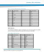
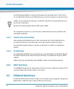
LEDS
describes the LEDs on the front panel of the MVME8100 / MVME8110. Refer to
for LED locations.
Table 3-14 Front Panel LEDs
Label
Function
Color
Description
USER 1 (D16)
User Defined
Off
By Default
Yellow
User Software Controllable.
Red
User Software Controllable.
FAIL (D8)
Board Fail
Off
Normal operation after
successful firmware boot
Red
One or more on-board power
rails have failed and the board
has shutdown to protect the
hardware. Normal during
power up, during hardware
reset (such as a front panel
reset). May be asserted by the
BDFAIL bit in the Tsi148 VSTAT
register
SPEED (J4)
Link/Speed
Off
No link
Amber
10/100BASE-T operation
Green
1000 BASE-T operation
ACT (J4)
Activity
Off
No activity
Blinking Green
Activity proportional to
bandwidth utilization
Summary of Contents for MVME8100
Page 1: ...MVME8100 MVME8110 Installation and Use P N 6806800P25J August 2015 ...
Page 8: ...MVME8100 MVME8110 Installation and Use 6806800P25J 8 List of Tables ...
Page 10: ...MVME8100 MVME8110 Installation and Use 6806800P25J 10 List of Figures ...
Page 26: ...MVME8100 MVME8110 Installation and Use 6806800P25J Sicherheitshinweise 26 ...
Page 58: ...Hardware Preparation and Installation MVME8100 MVME8110 Installation and Use 6806800P25J 58 ...
Page 84: ...Connectors LEDs and Switches MVME8100 MVME8110 Installation and Use 6806800P25J 84 ...
Page 108: ...Functional Description MVME8100 MVME8110 Installation and Use 6806800P25J 108 ...
Page 122: ...Related Documentation MVME8100 MVME8110 Installation and Use 6806800P25J 122 ...
Page 123: ......


