Functional Description
MVME8100 / MVME8110 Installation and Use (6806800P25J)
89
4.4.1
Real Time Clock
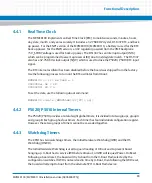
The MVME8100 implements an Real Time Clock (RTC) to maintain seconds, minutes, hours,
day, date, month, and year accurately. It includes a 32.768 KHZ crystal, DS1337 RTC, and back
up power. For the ENP1 version of the MVME8100 / MVME8110, a battery is used for the RTC
back up power. For the ENP4 version, a 3.3V regulator powered from the VME backplane
+5V_STDBY voltage is used for back up power. The DS1337 has an interrupt output (INTA)
which can be programmed to assert a processor IRQ on a time/day/date match. The DS1337
also has a 32.768 KHz clock output (SQW) which is used to drive the P5020 / P5010 RTC input
signal.
The RTC internal oscillator has been disabled before the board was shipped from the factory.
Use the following process to turn on the RTC oscillator from Uboot:
MVME8100 => i2c mm 0x68 e.1
0000000e: 98 ? 18
0000000f: 80 ? n
To set the date, use the following uboot command:
MVME8100 =>date [MMDDhhmm[[CC]YY][.ss]]
4.4.2
P5020/ P5010 Internal Timers
The P5020/ P5010 provides a total of eight global timers; it is divided into two groups, group A
and group B. Each group has four timers. Each timer has four individual configuration register.
However, these two groups of timers cannot be cascaded together.
4.4.3
Watchdog Timers
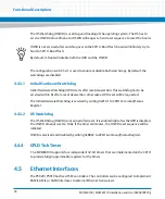
The CPLD has two watchdogs timers, the Initial Hardware Watchdog (IWD) and the OS
Watchdog (OSWD).
The Initial Hardware Watchdog is used to guard loading of U-Boot and to prevent board
hanging up. U-Boot has to service IWD before timeout, or IWD will request Power-On Reset.
Following a board reset, the board will try to boot from the U-Boot Flash selected by the
configuration switches. If IWD is not serviced in time by U-Boot, then following the IWD reset,
the board will attempt to boot from the alternate SPI1 U-Boot Flash device.
Summary of Contents for MVME8100
Page 1: ...MVME8100 MVME8110 Installation and Use P N 6806800P25J August 2015 ...
Page 8: ...MVME8100 MVME8110 Installation and Use 6806800P25J 8 List of Tables ...
Page 10: ...MVME8100 MVME8110 Installation and Use 6806800P25J 10 List of Figures ...
Page 26: ...MVME8100 MVME8110 Installation and Use 6806800P25J Sicherheitshinweise 26 ...
Page 58: ...Hardware Preparation and Installation MVME8100 MVME8110 Installation and Use 6806800P25J 58 ...
Page 84: ...Connectors LEDs and Switches MVME8100 MVME8110 Installation and Use 6806800P25J 84 ...
Page 108: ...Functional Description MVME8100 MVME8110 Installation and Use 6806800P25J 108 ...
Page 122: ...Related Documentation MVME8100 MVME8110 Installation and Use 6806800P25J 122 ...
Page 123: ......


