


Connectors, LEDs, and Switches
MVME8100 / MVME8110 Installation and Use (6806800P25J)
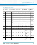
71
2
JTAG TRST
34
IDSELB
3
JTAG TMS
35
TRDY
4
JTAG TDO
36
+3.3V
5
JTAG TDI
37
GND
6
GND
38
STOP
7
GND
39
PERR
8
NC
40
GND
9
NC
41
+3.3V
10
NC
42
SERR
11
BUSMODE2
(Pulled UP)
43
CBE1
12
+3.3V
44
GND
13
PCI RESET
45
AD 14
14
BUSMODE3
(PULLED DWN)
46
AD 13
15
+3.3V
47
M66EN
16
BUSMODE4
(PULLED DWN)
48
AD 10
17
NC
49
AD 8
18
GND
50
+3.3V
19
AD 30
51
AD 7
20
AD 29
52
REQB
21
GND
53
+3.3V
22
AD 26
54
GNTB
23
AD 24
55
NC
24
+3.3V
56
GND
25
IDSEL
57
NC
26
AD 23
58
EREADY
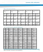
Table 3-9 PMC J12/J22 Connector (continued)
Pin Name
Signal Description Pin Name
Signal Description
Summary of Contents for MVME8100
Page 1: ...MVME8100 MVME8110 Installation and Use P N 6806800P25J August 2015 ...
Page 8: ...MVME8100 MVME8110 Installation and Use 6806800P25J 8 List of Tables ...
Page 10: ...MVME8100 MVME8110 Installation and Use 6806800P25J 10 List of Figures ...
Page 26: ...MVME8100 MVME8110 Installation and Use 6806800P25J Sicherheitshinweise 26 ...
Page 58: ...Hardware Preparation and Installation MVME8100 MVME8110 Installation and Use 6806800P25J 58 ...
Page 84: ...Connectors LEDs and Switches MVME8100 MVME8110 Installation and Use 6806800P25J 84 ...
Page 108: ...Functional Description MVME8100 MVME8110 Installation and Use 6806800P25J 108 ...
Page 122: ...Related Documentation MVME8100 MVME8110 Installation and Use 6806800P25J 122 ...
Page 123: ......


