


Functional Description
MVME8100 / MVME8110 Installation and Use (6806800P25J)
91
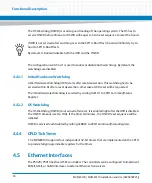
The MVME8100 / MVME8110 utilizes dTSEC4 for a dedicated front panel 10/100/1000BASE-T
interface and dTSEC5 for a 10/100/1000BASE-T interface to the RTM via P2. A Broadcom
BCM5482 dual transceiver provides the RGMII -> 10/100/1000BASE-T interfaces. A second
10/100/1000BASE-T interface to the RTM through P2 is provided using dTSEC3 in SGMII mode.
A Broadcom BCM54616S transceiver provides the SGMII -> 10/100/1000BASE-T interface. The
registers of these transceivers can be accessed via the P5020 / P5010's two-wire Ethernet
Management interface.
The front panel RJ45 connector has integrated speed and activity status indicator LED's. Similar
to the front panel Ethernet, the RJ45 connectors found in the RTM have integrated speed and
activity status indicator LED's. Isolation transformers are provided on-board for each of the
RTM ports.
The MVME8100utilizes dTSEC1 and dTSEC2 in SGMII mode for two additional 1000Base-BX
Ethernet ports to P0.
4.6
SPI Interface
Firmware boot Flash resides on the P5020 / P5010 eSPI bus interface.
4.6.1
SPI Flash Memory
The P5020 / P5010 contains two Eight MB serial flash devices. These devices contain the 512
bits of the Reset Configuration Word, the boot firmware image (U-boot), and the ENV
environment variables.
4.6.2
Firmware Redundancy
The MVME8100 / MVME8110 utilizes two separate Eight MB boot devices in order to provide
boot firmware redundancy. The P5020 / P5010 SPI device controller uses Chip Select 0 as the
boot device, so CPLD logic is used on the MVME8100 / MVME8110 in order to swap the chip
select to the boot devices. The chip select control is based upon the configuration switch S5-1.
At power-up, the selection of the SPI boot device is strictly based upon the switch S5-1 setting.
The selected SPI device must contain a boot image. The MVME8100 / MVME8110 supports
automatic SPI FLASH fail-over. If booting on one device is not successful, then the watchdog will
trigger a board reset and the CPLD logic automatically toggle chip selects, and tries to boot on
the other device.
Summary of Contents for MVME8100
Page 1: ...MVME8100 MVME8110 Installation and Use P N 6806800P25J August 2015 ...
Page 8: ...MVME8100 MVME8110 Installation and Use 6806800P25J 8 List of Tables ...
Page 10: ...MVME8100 MVME8110 Installation and Use 6806800P25J 10 List of Figures ...
Page 26: ...MVME8100 MVME8110 Installation and Use 6806800P25J Sicherheitshinweise 26 ...
Page 58: ...Hardware Preparation and Installation MVME8100 MVME8110 Installation and Use 6806800P25J 58 ...
Page 84: ...Connectors LEDs and Switches MVME8100 MVME8110 Installation and Use 6806800P25J 84 ...
Page 108: ...Functional Description MVME8100 MVME8110 Installation and Use 6806800P25J 108 ...
Page 122: ...Related Documentation MVME8100 MVME8110 Installation and Use 6806800P25J 122 ...
Page 123: ......


