


Connectors, LEDs, and Switches
MVME8100 / MVME8110 Installation and Use (6806800P25J)
69
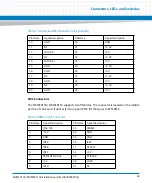
PMC Connectors
The MVME8100 / MVME8110 supports two PMC sites. The connector is located on the middle
portion of the board. It utilizes J14 to support PMC I/O that goes to RTM PMC.
10
GND
30
GND
11
NC
31
+3.3V
12
SATA RX -
32
+5V
13
NC
33
+3.3V
14
SATA RX +
34
+5V
15
GND
35
+3.3V
16
GND
36
+5V
17
NC
37
+3.3V
18
GND
38
+5V
19
NC
39
+3.3V
20
GND
40
+5V
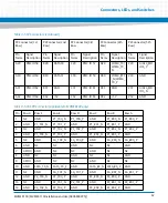
Table 3-8 PMC J11/J21 Connector
Pin Name
Signal Description
Pin Name Signal Description
1
JTAG TCK
33
FRAME
2
-12V
34
GND
3
GND
35
GND
4
INT A
36
IRDY
5
INT B
37
DEVSEL
6
INT C
38
+5V
7
PRESENT SIGNAL
39
PCIXCAP
8
+5V
40
LOCK
9
INT D
41
NC
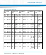
Table 3-7 Customized SATA Connector (J3) (continued)
Pin Name
Signal Description
Pin Name
Signal Description
Summary of Contents for MVME8100
Page 1: ...MVME8100 MVME8110 Installation and Use P N 6806800P25J August 2015 ...
Page 8: ...MVME8100 MVME8110 Installation and Use 6806800P25J 8 List of Tables ...
Page 10: ...MVME8100 MVME8110 Installation and Use 6806800P25J 10 List of Figures ...
Page 26: ...MVME8100 MVME8110 Installation and Use 6806800P25J Sicherheitshinweise 26 ...
Page 58: ...Hardware Preparation and Installation MVME8100 MVME8110 Installation and Use 6806800P25J 58 ...
Page 84: ...Connectors LEDs and Switches MVME8100 MVME8110 Installation and Use 6806800P25J 84 ...
Page 108: ...Functional Description MVME8100 MVME8110 Installation and Use 6806800P25J 108 ...
Page 122: ...Related Documentation MVME8100 MVME8110 Installation and Use 6806800P25J 122 ...
Page 123: ......


