


Functional Description
MVME8100 / MVME8110 Installation and Use (6806800P25J)
93
The four ports can be configured for RS-232 or RS-422/RS-485 modes. RS-232 mode supports
RX, TX, RTS and CTS signals. Only four wire full duplex RX/TX is supported in RS422/485 mode.
The signaling mode is selected through on board configuration switches on S2.
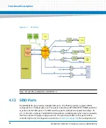
4.11 PCIe Ports
The MVME8100 / MVME8110 provides multiple PCI Express ports. The P5020/P5010 is
configured to use two x4 PCIe controllers (#1 and #3) on the MVME8100 / MVME8110. Both
controllers are configured to operate at Gen 1 data rate (2.5 Gbaud). These ports are routed to
an IDT 32NT24AG2 PCIe switch for expansion of the PCIe ports. The IDT switch is a 32 lane Gen
2 device and can support up to 24 ports, 8 of which are capable of NT function. Each port of the
switch is configured to operate at Gen 1 data rate. The configuration of the ports and the
partitioning of the switch into a single or multiple domains is controlled by an I2C eeprom
connected to the PCIe switch master SMbus and loaded into the switch following reset.
The board provides two separate eeproms so that separate configuration data can be
maintained for the MVME8100 / MVME8110 operating as a root complex or as an end point on
the P0 connector ports for MVME8100. The selection of the root complex or end point eeprom
for loading the configuration data after reset is determined by the root complex configuration
switch S4-2 (see
.). The eeproms can be reprogrammed from the
processor using the I2C master interface in the IDT device. A swap bit in CPLD control register
can be used to temporarily swap the eeprom device addressing so that the alternate eeprom
can be reprogrammed. A diagram of the PCIe port configuration is shown in the figure below.
Summary of Contents for MVME8100
Page 1: ...MVME8100 MVME8110 Installation and Use P N 6806800P25J August 2015 ...
Page 8: ...MVME8100 MVME8110 Installation and Use 6806800P25J 8 List of Tables ...
Page 10: ...MVME8100 MVME8110 Installation and Use 6806800P25J 10 List of Figures ...
Page 26: ...MVME8100 MVME8110 Installation and Use 6806800P25J Sicherheitshinweise 26 ...
Page 58: ...Hardware Preparation and Installation MVME8100 MVME8110 Installation and Use 6806800P25J 58 ...
Page 84: ...Connectors LEDs and Switches MVME8100 MVME8110 Installation and Use 6806800P25J 84 ...
Page 108: ...Functional Description MVME8100 MVME8110 Installation and Use 6806800P25J 108 ...
Page 122: ...Related Documentation MVME8100 MVME8110 Installation and Use 6806800P25J 122 ...
Page 123: ......


