


Connectors, LEDs, and Switches
MVME8100 / MVME8110 Installation and Use (6806800P25J)
61
3.1.1
External Connectors
3.1.1.1
Front Panel Connectors
The following are the Front Panel Connectors:
Serial Console Port (J1)
Front Panel Ethernet Connector (J1)
USB Connector (J5)
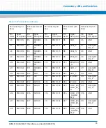
Table 3-1 Console Front Panel Connector (J1)
PIN No
RS232 SIGNALING
RS485 SIGNALING
1
NC
NC
2
COM_0_RX
COM_0_RX-
3
COM_0_TX
COM_0_TX-
4
NC
NC
5
GND
GND
6
NC
NC
7
COM_0_RTS
8
COM_0_CTS
9
NC
NC
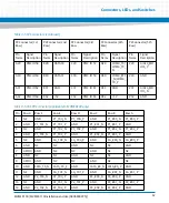
Table 3-2 Front Panel Tri- Speed Ethernet Connector (J4)
Note: J4 is assembled only on ENP1
Pin No
Signal Description
1
VCC
2
TD0+
3
TD0-
4
TD1+
5
TD2+
6
TD2-
Summary of Contents for MVME8100
Page 1: ...MVME8100 MVME8110 Installation and Use P N 6806800P25J August 2015 ...
Page 8: ...MVME8100 MVME8110 Installation and Use 6806800P25J 8 List of Tables ...
Page 10: ...MVME8100 MVME8110 Installation and Use 6806800P25J 10 List of Figures ...
Page 26: ...MVME8100 MVME8110 Installation and Use 6806800P25J Sicherheitshinweise 26 ...
Page 58: ...Hardware Preparation and Installation MVME8100 MVME8110 Installation and Use 6806800P25J 58 ...
Page 84: ...Connectors LEDs and Switches MVME8100 MVME8110 Installation and Use 6806800P25J 84 ...
Page 108: ...Functional Description MVME8100 MVME8110 Installation and Use 6806800P25J 108 ...
Page 122: ...Related Documentation MVME8100 MVME8110 Installation and Use 6806800P25J 122 ...
Page 123: ......


