11
INSTALLATION
6.2
Monitor and control unit location
•
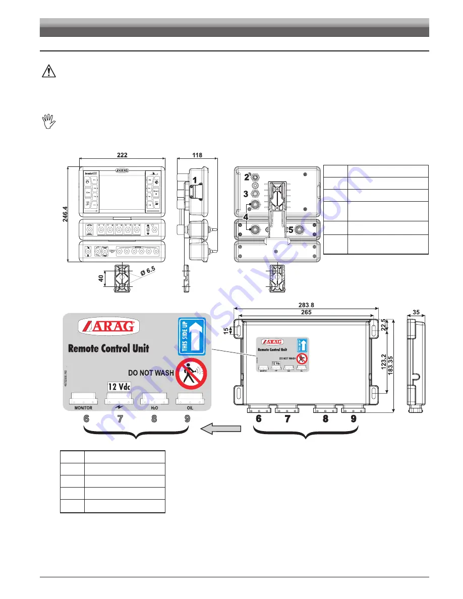
The BRAVO 400 series computer must be installed in the machine control cabin. Observe the following precautions:
- do NOT install the monitor in areas where it would be subjected to excessive vibrations or shocks, to prevent any damage or
accidental use of the control keys;
- install the device in a visible position within easy reach by hand; bear in mind that the computer should not obstruct the
operator’s freedom of movement or block his view.
• Control unit (RCU): locate the control unit in the rear side of the machine near the control unit and the oil-hydraulic/pneumatic
assemblies.
Note the connections required for the computer to operate (Fig. 6 and 7), the required length of the cables, and provide adequate
space for connectors cables.
An identification symbol is located next to each connector to indicate its function. For the configuration of the systems, refer to
par. 6.1 - Recommended system layout.
Fig. 6
item
connection pointS
1
SD memory card
2
Connection to GPS receiver
3
Connection to cameras
+
External main control
4
Connection
to switches panel / monitor
5
Control panel power supply
+
Connections to RCU
Fig. 7
item
connection pointS
6
Monitor
7
Power and sensors
8
Control unit
9
Oil-hydraulic assembly
Summary of Contents for 46742DX1
Page 6: ...Notes 6...
Page 94: ...Notes 94...


