background image

Setup 

Document No. D113-015  


Page 11 of 77 

Revision 1.9  

3.


SETUP 

3.1.


INSTALL CONFIGURATION SOFTWARE 


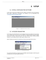
All the network setup and configuration of the module is achieved by means of the Aparian 

Slate  device  configuration  environment.  This  software  can  be  downloaded  from 

http://www.aparian.com/software/slate


Figure 3.1. - Aparian Slate Environment 

3.2.


NETWORK PARAMETERS 


The module will have DHCP (Dynamic Host Configuration Protocol) enabled as factory default. 

Thus,  a  DHCP  server  must  be  used  to  provide  the  module  with  the  required  network 
parameters (IP address, subnet mask, etc.). There are a number of DHCP utilities available, 

however it is recommended that the DHCP server in Slate be used. 


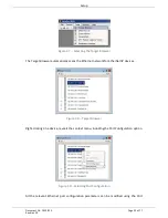
Within the Slate environment, the DHCP server can be found under the Tools menu. 


Figure 3.2. - Selecting DHCP Server 


Once opened, the DHCP server will listen on all available network adapters for DHCP requests 

and display their corresponding MAC addresses. 

Summary of Contents for A-HRT-4I

Page 1: ...HART 4 Devices User Manual A HRT 4I A HRT 4O Document No D113 015 07 2018 Revision 1 9...

Page 2: ...ork Parameters 11 3 3 Creating a New Project 15 3 4 HART 4 parameters 17 3 5 Module Download 26 3 6 Logix Integration 28 3 6 1 Add Module to I O Configuration 28 3 6 2 Importing UDTs and Mapping Routi...

Page 3: ...ion Date Comment 1 0 13 Apr 2016 Initial document 1 1 26 June 2016 Updated temperature range 1 2 11 August 2016 Added RoHS2 compliant to certifications 1 3 24 September 2016 Added ODVA EtherNet IP Con...

Page 4: ...s a Modbus Slave The DNP3 option converts a HART field device into a DNP3 Outstation The DNP3 option also supports Secure Authentication ensuring secure communications across the Ethernet network In a...

Page 5: ...tion guide cde205_220_420_hig Connectors html Table 1 1 Additional Information 1 3 REFERENCES Resource Link HART Communication Foundation http en hartcomm org DNP3 http www dnp org CIP Routing The CI...

Page 6: ...ctor which is used for the DC power supply and the earth connection The Ethernet cable must be wired according to industry standards which can be found in the additional information section of this do...

Page 7: ...rce the module into Safe Mode When in Safe Mode the module will not load the application firmware and will wait for new firmware to be downloaded This should only be used in the rare occasion when a f...

Page 8: ...pecification The DIN rail clip is mounted on the bottom of the module at the back as shown in the figure below Use a flat screw driver to pull the clip downward This will enable the user to mount the...

Page 9: ...ls are connected using a two way connector The input channels A HRT 4I are internally loop powered and therefore can be connected directly to the field device signal terminals The output channels A HR...

Page 10: ...9 Figure 2 7 Analog Input Equivalent Circuit Figure 2 8 Analog Output Equivalent Circuit 2 5 ETHERNET PORT The Ethernet connector should be wired according to industry standards Refer to the additiona...

Page 11: ...module will have DHCP Dynamic Host Configuration Protocol enabled as factory default Thus a DHCP server must be used to provide the module with the required network parameters IP address subnet mask e...

Page 12: ...n The IP Address Assignment window will open Figure 3 4 Assigning IP Address The required IP address can then be either entered or a recently used IP address can be selected by clicking on an item in...

Page 13: ...mode after the power is cycled again If the module s DIP switch 2 is in the On position during the address assignment the user will be warned by the following message Figure 3 6 Force DHCP warning In...

Page 14: ...r automatically scans the Ethernet network for EtherNet IP devices Figure 3 8 Target Browser Right clicking on a device reveals the context menu including the Port Configuration option Figure 3 9 Sele...

Page 15: ...10 Port Configuration Alternatively these parameters can be modified using Rockwell Automation s RSLinx software 3 3 CREATING A NEW PROJECT Before the user can configure the module a new Slate projec...

Page 16: ...d under the Device menu Figure 3 12 Adding a new device In the Add New Device window select the HART 4In or HART 4Out module and click the Ok button The configuration of the HART 4In and HART 4Out mod...

Page 17: ...METERS The HART 4 module parameters are configured using the Slate configuration utility The configuration form is divided into multiple tabs to configure the general DNP3 and channel specific paramet...

Page 18: ...e device will respond as a Modbus TCP slave DNP3 TCP When selected the device will respond as a DNP3 Outstation using a TCP DNP3 UDP When selected the device will respond as a DNP3 Outstation using a...

Page 19: ...s value when the current is equal to the Raw Min value Filter The time constant in milliseconds of the first order filter applied to the analog signal A value of zero implies no filtering HART Communi...

Page 20: ...output value to the adjacent Fail Value when a program or fault state is detected This option is only valid when using the EtherNet IP protocol Fail Value Prog Fault The value in engineering units to...

Page 21: ...Setup Document No D113 015 Page 21 of 77 Revision 1 9 Figure 3 16 Channel configuration HART 4In Figure 3 17 Channel configuration HART 4Out...

Page 22: ...parameter See Advanced Diagnostic Builder below Data Type The Logix tag data type required to accept the parameter Logix Tag The Logix tag name mapped to receive the parameter Table 3 3 Advanced Diagn...

Page 23: ...de decimal Command Length This is the length of the data that must be sent with the command Result Offset The byte offset in the response where the required parameter starts Data Type The Logix tag da...

Page 24: ...changed between two devices Currently the HART 4 only supports the Pre Shared Key method This method requires both devices to have update keys entered by means outside the DNP3 protocol i e using Slat...

Page 25: ...n functions that must be authenticated before data can be exchanged The optional functions can be selected in the box Mandatory functions e g Operate are therefore not included in the options list Tab...

Page 26: ...ress of the module as set in the module configuration It can however be modified if the HART 4 module is not on a local network The Connection path can be set by right clicking on the module and selec...

Page 27: ...the user will be notified that the download was successful Figure 3 25 Successful download Within the Slate environment the module will be in the Online state indicated by the green circle around the...

Page 28: ...cted to be added as shown in the figure below NOTE See the next section for importing the configuration L5X Figure 3 27 Add a Generic Ethernet Module in RSLogix 5000 NOTE The module configuration for...

Page 29: ...e properties for HART 4In module The required connection parameters for the HART 4Out module are shown below Connection Parameter Assembly Instance Size Input 113 119 32 bit Output 115 4 32 bit Config...

Page 30: ...anged The recommended value is 200ms Refer to the technical specification section in this document for further details on the limits of the RPI Figure 3 30 Connection module properties in RSLogix 5000...

Page 31: ...INES To simplify the mapping of the input image an RSLogix 5000 Routine Partial Import L5X file is provided This file can be imported by right clicking on the required Program and selecting the Import...

Page 32: ...mapping the HART4In and HART4Out modules to the aforementioned tags The user may need to change the routine to map to the correct HART 4 module instance name and make sure that the mapping routine is...

Page 33: ...Setup Document No D113 015 Page 33 of 77 Revision 1 9 Figure 3 35 UDT Input Assembly...

Page 34: ...the general HART 4 module configuration in Slate Temperature REAL The internal temperature of the module in C Module Status DINT Bit 0 Configuration Valid Bit 1 Channel 0 Enabled Bit 2 Channel 1 Enab...

Page 35: ...ow BOOL Field device receive buffer overflow Chx_HARTStatus ValueTooLarge BOOL Value too large in previous HART command Chx_HARTStatus ValueTooSmall BOOL Value too small in previous HART command Chx_H...

Page 36: ...REAL Fourth Variable in engineering units Chx_PVUnitCode SINT Primary Variable engineering units code Chx_SVUnitCode SINT Secondary Variable engineering units code Chx_TVUnitCode SINT Third Variable e...

Page 37: ...3_Data REAL Analog output value in engineering units for Channel 3 Table 4 2 HART 4Out Logix 5000 output assembly parameters 4 1 3 HART RELAY MESSAGE The module supports the relaying of custom HART co...

Page 38: ...vice Type Custom Service Code 79 Hex Relay HART Message service Class 40F Hex Instance Channel value 1 1 for Channel 0 2 for Channel 1 3 for Channel 2 4 for Channel 3 Attribute 0 Source Element Tag of...

Page 39: ...required Table 4 4 Relay HART Message Request Structure HART Command Response Byte Offset Data Type Description 0 INT Status See table below 2 INT Packet Length 4 SINT Start Character 5 SINT Long Addr...

Page 40: ...ut current fixed 4 Undefined 5 Cold Start 6 Configuration Changed Table 4 6 Status Decoding when first byte bit 7 0 If Byte 0 Bit 7 1 then First Byte Communication Errors Bit Description 0 Undefined 1...

Page 41: ...Operation Document No D113 015 Page 41 of 77 Revision 1 9 Figure 4 3 Relay HART Message Example Configuration Figure 4 4 Relay HART Command Example Request...

Page 42: ...on 1 9 Figure 4 5 Relay HART Command Example Response NOTE The HART Long Address for a device is comprised of the Manufacturer ID Device Type Code and Device ID These values are displayed on the Chann...

Page 43: ...Sent 1 5 Error Messages Received 1 6 Checksum Error 1 7 HART Tx Count 1 20 30 40 50 HART Rx Count 1 21 31 41 51 Communication Errors 1 22 32 42 52 Command Errors 1 23 33 43 53 Time Out Errors 1 24 34...

Page 44: ...ber of Preambles Required 1 102 202 302 402 Universal Command Rev 1 103 203 303 403 Specific Command Rev 1 104 204 304 404 Software Rev 1 105 205 305 405 Hardware Rev 1 106 206 306 406 Device Function...

Page 45: ...be entered into each device by means outside of the DNP3 protocol In Slate the user can write the Update Key into the HART 4 module using the Key tab in the Online Status window The key entered must m...

Page 46: ...3 MODBUS TCP OPERATION The Modbus TCP operation is enabled when the configuration protocol is set to either Modbus TCP The HART 4 module will then operate as a Modbus TCP Slave supporting the followin...

Page 47: ...TE 3 106 206 306 406 Units Code for Sensor 1 BYTE Sensor Upper Limit 4 REAL 108 208 308 408 Sensor Lower Limit 4 REAL 110 210 310 410 Sensor Minimum Span 4 REAL 112 212 312 412 Tag 8 BYTE 8 114 214 31...

Page 48: ...Device Specific Status 0 6 BYTE 6 402 502 602 702 Operational Modes 2 BYTE 2 405 505 605 705 Standardized Status 0 1 BYTE 406 506 606 706 Standardized_status1 1 BYTE Analog channel saturated 1 BYTE 40...

Page 49: ...e will have a red Module LED If the LED is green then the module has booted and is running correctly Ethernet The Ethernet LED will light up when an Ethernet link has been detected by plugging in a co...

Page 50: ...in full by Slate or using the web server in the module To view the module s status in the Aparian Slate environment the module must be online If the module is not already Online following a recent co...

Page 51: ...gure 5 4 Status monitoring General The General tab displays the following general parameters and can also be used to set the module time to the PC time Parameter Description Protocol Indicates the cur...

Page 52: ...TUS Figure 5 5 EtherNet IP Statistics Statistic Description Class 1 Timeout Count The number of Class 1 connections closed due to Timeouts Class 3 Timeout Count The number of Class 3 connections close...

Page 53: ...is enabled Messages Discarded The number of DNP3 packets discarded by the module Error Messages Tx The number of error DNP3 packets sent by the module Error Messages Rx The number of error DNP3 packe...

Page 54: ...match the Hart 4 module configured node address Select Size Too Large When the Select Operate functionality is used the Hart 4 module supports a maximum of 255 bytes per transaction or one full DNP3...

Page 55: ...cation is not supported this will increase MAC Algorithm Not Supported The MAC algorithm requested is not supported Key Wrap Algorithm Not Supported The Key Wrap algorithm requested is not supported U...

Page 56: ...e responded with an Illegal Function exception Illegal Data Address The number of times the Modbus device responded with an Illegal Data Address exception Illegal Data Value The number of times the Mo...

Page 57: ...that specific channel The General tab displays a summary of the common HART parameters Figure 5 10 Channel Status General Parameter Description Tag The user tag name configured in the field device 8...

Page 58: ...t enumeration Table 5 7 Channel Status Parameters General The Device Info tab displays a more detailed information of the field device Figure 5 11 Channel Status Device Info Parameter Description Manu...

Page 59: ...device Sensor Minimum Span The minimum span allowed by the sensor Table 5 8 Channel Status Parameters Device Info The Device Status tab displays the status of the analog and HART interaction with the...

Page 60: ...if the field device has detected an error or suffered some hardware failure Config Changed Flagged if an operation resulted in the configuration changing Cold Start Flagged if the field device has ex...

Page 61: ...nge Units are updated together Damping The damping value specified in seconds Damping refers to the digital filtering of process variables to remove transient and potentially erroneous deviations from...

Page 62: ...consult the field device manufacturer s documentation for more information Figure 5 15 Channel Status Advanced Status The HART Statistics tab displays the communication statistics Figure 5 16 Channel...

Page 63: ...imeouts The number of advanced diagnostic reads where no reply was received Table 5 11 Channel Status Parameters HART Communication Statistics The PV Tracking Status tab displays the current minimum a...

Page 64: ...ected 5 4 DEVICE LIST The module supports scanning the channel to determine at which short address the field device s are The user can select the start and end address to minimize the scan time Once t...

Page 65: ...xecute per device found in the device list Some of the options will only be relevant depending on the HART Rev eg the Long Tag is only support with HART 6 7 Figure 5 20 Device List Options 5 5 CALIBRA...

Page 66: ...ual numeric inputs 3 Press the Low Value 4mA Capture button to capture the current un calibrated value into the Raw Capture field 4 Using the external milliamp source adjust the current to 20mA or as...

Page 67: ...al meter measure the actual loop current and enter the milliamp value in the High Value 20mA Actual Measured textbox 6 The new Span and Offset calibration settings will be automatically calculated See...

Page 68: ...in the Project Explorer tree Figure 5 24 Selecting the module Event Log The Event Log window will open and automatically read all the events from the module The log entries are sorted so as to have th...

Page 69: ...ing a user without Slate or RSLogix 5000 to view various diagnostics of the module This includes Ethernet parameters system event log advanced diagnostics and application diagnostics NOTE The web serv...

Page 70: ...ts FDT DTM technology allowing the user to configure any field device using its DTM Device Type Manager in any standard FDT Frame Field Device Tool To use a field device DTM with the HART 4 module the...

Page 71: ...SK As the name implies FSK changes the frequency of the carrier to represent the binary data 0 or 1 A frequency of 1200 Hz represents a logical 1 and a frequency of 2200 Hz represents a logic 0 Theref...

Page 72: ...of 77 Revision 1 9 8 TECHNICAL SPECIFICATIONS 8 1 DIMENSIONS Below are the enclosure dimensions as well as the required DIN rail dimensions All dimensions are in millimetres Figure 8 1 HART 4 module e...

Page 73: ...input channels shorted HART 4In Connector Power 3 way terminal Connector Analog 2 way terminal Conductors 24 18 AWG Enclosure rating IP20 NEMA UL Open Type Temperature 20 70 C Earth connection Yes te...

Page 74: ...47 5 Accuracy calibrated 25 C 0 15 Accuracy uncalibrated 0 30 Range 0 22 mA Current limit 34 mA Table 8 3 Analog Input channel specification 8 5 ANALOG OUTPUT CHANNEL HART 4 OUT Specification Rating N...

Page 75: ...Technical Specifications Document No D113 015 Page 75 of 77 Revision 1 9 RoHS2 Compliant ODVA Conformance F W 1 004 RCM Table 8 5 Certifications...

Page 76: ...34 44 HART 4 general configuration 18 HART 4 parameters 17 HART Advanced Status 60 HART Channel 9 HART Channel Status 55 HART Device Info 56 HART Device Status 57 HART relay message 37 HART 4In 28 HA...

Page 77: ...Index Document No D113 015 Page 77 of 77 Revision 1 9 T Target Browser 13 Trending 62 U UDT 33 Update Key 43 44 52 53 User Defined Types UDTs 30 W Web server 48 67...

Reviews: