Diagnostics
Document No. D113-015
Page 67 of 77
Revision 1.9
NOTE
: Before commencing with input calibration ensure that it is safe to do
so. The simulated current values could translate to extreme process variables
in the connected control system which may cause unexpected results. Failure
to do so could result in severe equipment damage and personal injury.
5.5.2.
O
UTPUT
C
ALIBRATION
:
To re-calibrate a HART 4 Output module:
1.
Ensure the channel configuration has both the
Prog/Fault Freeze
and
Comm Fail Freeze
options
checked, and that the module is disconnected from the EtherNet/IP (Logix), DNP3 or Modbus source.
2.
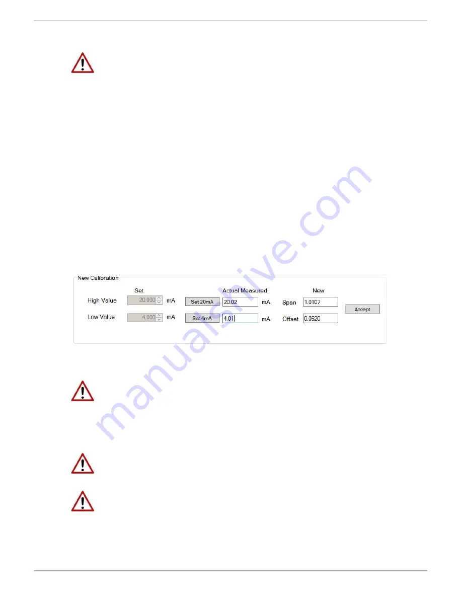
Click the
Set 4mA
button. The output current will change to 4mA.
3.
Using an external meter, measure the actual loop current and enter the milliamp value in the
Low Value
(4mA)
Actual Measured
textbox.
4.
Click the
Set 20mA
button. The output current will change to 20mA.
5.
Using an external meter, measure the actual loop current and enter the milliamp value in the
High
Value
(20mA)
Actual Measured
textbox.
6.
The new
Span
and
Offset
calibration settings will be automatically calculated. (See figure below).
7.
Press
Accept
to write these new calibration figures to the module.
8.
The Calibration Type will then change to User Calibration, to reflect the changes.
Figure 5.23 – User Calibration - Output
NOTE
: Before commencing with output calibration ensure that it is safe to do
so. The field device should be either isolated from the process mechanically or
the process be in such a state that variations in the output signal cannot cause
a disruption to the process. Failure to do so could result in severe equipment
damage and personal injury.
NOTE
: The
Set 20mA
and
Set 4mA
buttons will be disabled if the configuration
has either the
Prog/Fault Freeze
or
Comm Fail Freeze
options not checked.
NOTE
: If the module’s data source (EtherNet/IP (Logix), DNP3 or Modbus) is
not disconnected or disabled, then the simulated milliamp value will be
constantly over-written negating the calibration procedure.


