ANDREOLI
ENGINEERING
Operator’s Manual
Self-propelled sprayer ATOM
153/166
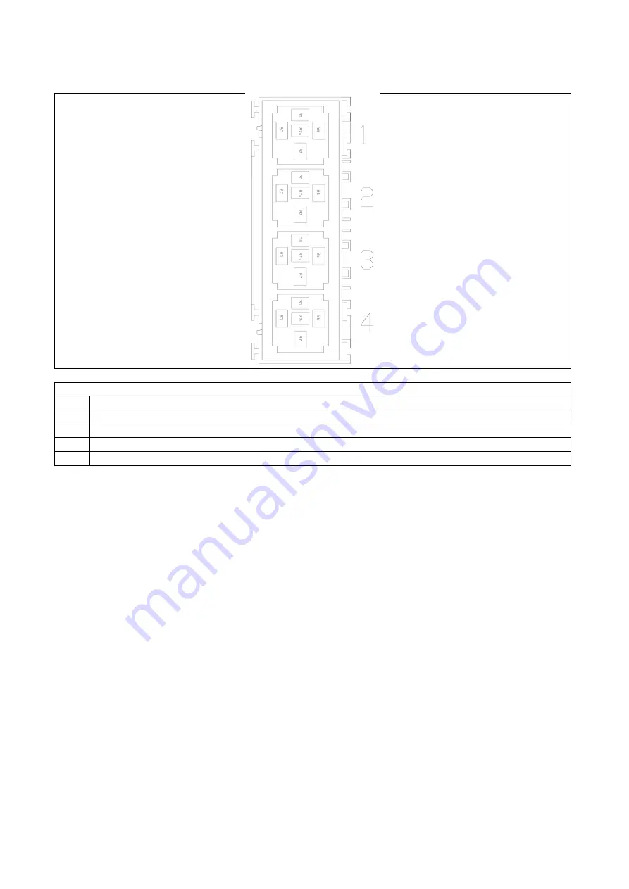
AUTOMATIC AC CONTROLLER RELAYS BOX
DESCRIPTION OF THE RELAYS Nr
Function
E1
AC Fan - 1 speed
E2
AC Fan - 2 speed
E3
AC Fan - 3 speed
E4
AC Compressor
Page 1: ...lf propelled sprayer ATOM 1 166 OPERATOR S MANUAL SELF PROPELLED SPRAYER Manufacturer ANDREOLI Type SPRAYER Model ATOM 1000 ATOM 2000 Carefully read this Manual before using the machine ENG Printed Fi...
Page 2: ...RING srl manufacturer and depositary of the technical record with legal office in via prov le Modena 68 B 41016 Novi di Modena MO ITALY declares under his responsibility that the machine Type SELF PRO...
Page 3: ...TY INSTRUCTIONS FOR DRIVING ON PUBLIC ROADS 21 2 13 SAFETY INSTRUCTIONS FOR STORAGE 21 2 14 SAFETY INSTRUCTIONS FOR MAINTENANCE 22 2 15 SAFETY INSTRUCTIONS FOR USE AFTER LONG STOP 23 2 16 SAFETY INSTR...
Page 4: ...Chemicals circuit layout 63 3 13 2 Chemicals tank 65 3 13 3 Chemicals tank disinfection 66 3 13 4 Tank level sensor 67 3 13 5 Chemicals tank agitators Standard chemicals circuit layout 68 3 13 6 Chem...
Page 5: ...PREPARATION 98 6 1 FAN BLOWER ENGAGEMENT 98 6 2 PERFORM SPRAYING OPERATIONS 99 6 2 1 Spraying with manual controls 99 6 2 2 Spraying with automatic controller 100 6 3 FLUSHING PROCEDURE FOR SPRAY EQUI...
Page 6: ...lator 139 7 13 4 Fast pressure regulator for automatic controller 140 7 13 5 Manual safety pressure regulator 141 7 13 6 Flowmeter 142 7 14 NOZZLES 143 7 15 CAB AIR FILTER 144 7 16 TYRE REPLACING 146...
Page 7: ...on could not exactly match with the delivered machine Additional annexed information are not prejudicing safety level It is possible that some devices described in this manual are not fitted on your m...
Page 8: ...wing shows directions references used in this manual FRONT LEFT SIDE RIGHT SIDE REAR 1 1 TECHNICAL DATA ATOM 1000 R754TE4 DIMENSIONS Length 5026 mm Width 1845 mm Height 1425 mm ENGINE Max power 50 kW...
Page 9: ...ht 1400 1510 mm ENGINE Max power 70 kW NOISE VIBRATIONS Acoustic pressure LPA 84 3 1 0 dBA According to UNI EN ISO 4254 1 Acoustic power LWA 115 4 0 9 dBA According to UNI EN ISO 4254 1 Vibrations at...
Page 10: ...sprayer has been designed exclusively to spray chemicals mixed with water The machine sprays the mixture of water and chemicals and carries the spray to the target vegetation The spray is produced by...
Page 11: ...the machine In this case the operator will be the only responsible Carefully read the instructions for use of the machine in this manual and on the machine The operator must fully understand all infor...
Page 12: ...d personnel Before using the machine the operator must read all instructions of this manual undertstand all functions and controls and must practise about the use of the machine Make sure you have wel...
Page 13: ...Make sure all scheduled service operations have been regularly done before using the machine Check the pressure of the tyres and inflate at the pressure level suitable for the type of tyres and the n...
Page 14: ...ral windows can be broken with the safety hammer and used as an emergency exit Do NOT sharp steer Do NOT steer at high speed 2 7 SAFETY INSTRUCTIONS FOR THE USE OF CHEMICALS AND ENVIRONMENT CONTAMINAT...
Page 15: ...main chemicals tank avoid dripping out Do NOT fill completely the tank It is necessary to leave an empty room for possible foam and allow the movement of the liquid during the application without leak...
Page 16: ...ill fuel in potentially dangerous environment fire risk or explosion risk Stop the engine before refuelling do not handle fuel in a closed room Fill up fuel tank outside in a well ventilated place wit...
Page 17: ...The operations of regulation and service have to be made after reading the manual of use and maintenance with the machine stopped and the key removed 2 ATTENTION DANGER of fluids under pressure Read...
Page 18: ...M 18 166 9 ATTENTION DANGER hoses under pressure consult the manual 10 ATTENTION DANGER you may get entangled Keep your hands off the rotating shaft 11 ATTENTION DANGER rotating components 14 Use prot...
Page 19: ...e Transport operations must be done only by qualified and trained staff To transport the machine use a truck of proper size and power Use loading ramps of proper length to avoid chocks against the bot...
Page 20: ...use a rigid rod well dimensioned for the weight of the machine Connect the towing rigid rod to the front hooks During the towing operations an operator must be on board of the towed machine The machi...
Page 21: ...ce to avoid damages Make sure only authorized staff can access the machine Make sure that the storage temperature ranges between 0 C and 40 C Make sure that the storage environment is well ventilated...
Page 22: ...am do NOT use the machine if you have not respected the scheduled maintenance program Keep constantly clean main components of the machine engine battery fuel tank etc to avoid fire risks due to dust...
Page 23: ...gs for oil leaks Check all clamps and fittings Grease all moving components Check that the machine has no damages Check that all mechanical components are functional and not rusty Execute service oper...
Page 24: ...of your country If the engine runs in a closed room make sure you have a correct ventilation and fresh air circulation to avoid dangerous concentration of exhaust gas Do NOT waste pollutant products s...
Page 25: ...type according to EN15695 1 Keep the floor of the cab clean Remove tools and personal objects or fix it in a safe secured way It is necessary to know the position and the functions of all the controls...
Page 26: ...Cab filter housing is placed on left hand side of steering column 1 Cab filter 2 Ventilation system fan 3 Filter cover Do NOT use this filter for operations other than spraying Disinfection operations...
Page 27: ...rearview mirrors If the machine is equipped with periscope also use the rearview mirror of the periscope If the machine is equipped with cameras also use the monitor in the cab linked to rear cameras...
Page 28: ...d aft adjust 2 Height adjustment button 3 Lumbar support 4 Backrest angle adjustment 5 Seat belts Mechanical seat 1 Fore and aft adjust 2 Height adjustment button 3 Backrest angle adjustment 4 Seat be...
Page 29: ...of a sudden brake or on steep slopes Some types of safety belts only need manual adjustment 3 1 5 Steer column It is possible to adjust the steer column inclination to improve driving comfort 1 Steer...
Page 30: ...Shock absorbers H Air bags working height Set the pressure of each air bag in order to set its height H at a value of about 80 90 mm Each air bag has to be inflated separately from the others 3 2 ENGI...
Page 31: ...lled sprayer ATOM 31 166 3 3 DRIVELINE 1 Front axle 2 Rear axle 3 Cardan shaft 4 Gear box Hi Low I II 5 Hydraulic motor Rabbit Turtle 1 Main hydraulic pump 2 Fan clutch and support case 3 Blower fan 4...
Page 32: ...1 Chemicals pump 2 Cardan shaft 3 Gear box for chemicals pump 4 Clucth for chemicals pump 5 Main cooler 6 A C condenser Gear pumps for hydraulic services are connected to engine PTO 1 Gear pump for s...
Page 33: ...negative hydraulic type or mechanical type 3 4 1 Emergency brake pedal Emergency pedal brake is located on the right side of the steer column It engages the oil immerged discs brakes on the front axl...
Page 34: ...tatic pump If the pressure goes below this value the park brake lamp on the main instrument will switch on If the park brake turns on with the engine running and without acting on the park brake switc...
Page 35: ...to tow it you must unlock mechanically the negative brake 1 Screw 2 Spacer Loosen completely the two screws 1 from the axle body remove the spacer 2 and screw again the screws 1 in their original posi...
Page 36: ...ATOM 36 166 3 4 4 Mechanical parking brake Mechanical emergency brake and parking brake are both located in the drum on the front axle Mechanical parking brake can be activated by the lever placed on...
Page 37: ...n whenever the sensor reads the bolt and generates the pulse 1 Light 2 Head Head of speed sensor must be clean Periodically check and clean removing dust and particles Distance between sensor head and...
Page 38: ...TO TOP OF TANK STEP The machine is equipped with a sliding step to access the top of the tank 1 Step 2 Step lock Turn the lock 90 Pull the step out Do NOT run the machine with the step out Remember t...
Page 39: ...BATTERY AND MAIN SWITCH Battery and Main switch are located on the right side of the machine under the engine covers 1 Battery 2 Main switch 3 8 TANKS The following drawing shows tanks fitted on the...
Page 40: ...NEERING Operator s Manual Self propelled sprayer ATOM 40 166 3 9 MECHANICAL SUSPENSIONS The following drawing shows mechanical springs on front axle 1 Spring 2 Shock absorbers 3 Pins 1 Spring 2 Pins 1...
Page 41: ...ANDREOLI ENGINEERING Operator s Manual Self propelled sprayer ATOM 41 166 3 10 AXLES RIGID SUPPORTS The following drawing shows rigid pivot support of front axle 1 Shaft 2 Support 1 2 2...
Page 42: ...micals pump 5 Enable Sprayer fan 6 Chemicals circuit pressure regulation 7 Steer mode selection 4 steering wheels work mode 2 steering wheels road mode 4 steering wheels in phase lateral shift crab st...
Page 43: ...of the steering column Pushing the button the engine stops immediately and all other devices and moving parts of the machine will stop To start again the machine rotate the red button and pull it out...
Page 44: ...consequently the straight position of wheels On the dashboard L22 light turns on whenever front axle wheels are straight L23 light turns on whenever back axle wheels are straight L22 Front axle wheel...
Page 45: ...Engine Low Oil Pressure L3 Parking brake L4 Air filter clogging indicator L5 Transmission oil temperature warning light L6 Not used L7 Driving beams L8 Crossing beams L9 Engine Cold Start L10 Positio...
Page 46: ...E ERRORS with the number of engine errors and their codes If more than 1 error are detected the display shows each of them cyclically every 3 seconds L17 DPF Clogged Lamp Regeneration request L18 Engi...
Page 47: ...Air filter clogging indicator L7 Transmission oil temperature warning light L8 Not used L9 Driving beams L10 Crossing beams L11 Position lights L12 Low fuel level L13 Engine pre heating L19 High temp...
Page 48: ...prayer ATOM 48 166 3 11 2 Side dashboard 1 Automatic A C controller optional 2 Diagnostic plug for Main Instrument On Board CPU 3 Diagnostic plug for Engine ECU 4 Control switches for extra functions...
Page 49: ...pressed button 2 The display shows following information Tank level Percentage bar of tank level Pressure of chemicals circuit at the sections valves measurement point closest to the nozzles By pressi...
Page 50: ...he display can be done through the main menu To enter main menu keep pressed buttons 3 and 4 for 2 seconds It is possible to set different alarms min max pressure of chemicals circuit min max tank lev...
Page 51: ...e Total 1 and Volume Total 2 can be used to measure the quantity of chemicals sprayed total liters gallons sprayed If you select to display Volume Total 1 the current value of quantity of chemicals sp...
Page 52: ...he display can be done through the main menu To enter main menu keep pressed buttons 3 and 4 for 2 seconds It is possible to set different alarms min max flowrate min max speed min max application rat...
Page 53: ...rs Main Joystick A Forward direction B Reverse direction C Stop Main joystick has a safety lock in stop position C To move the joystick from the stop position incline it to the left side and then push...
Page 54: ...Work speed I slow B Road speed II fast C Neutral NOTE when the Hi Low lever is neutral position it is possible to tow the machine Main Joystick HL1 Left nozzle section ON light SW1 Left nozzle sectio...
Page 55: ...it again into neutral this will make the hydraulic motor and gears turning for a while helping the new gear to find its position easily 3 11 6 Command box of switches Machine can be equipped with a c...
Page 56: ...controller is installed only main ON OFF for nozzles sections can be present on main joystick connected to the controller When the controller is installed spray pressure can be adjusted using the swi...
Page 57: ...tap Use knob 2 to activate A C compressor When the compressor is on the A C lamp on main instrument will light on When the set temperature in the evaporator is reached the compressor will turn off and...
Page 58: ...ot work Thermostat has a temperature probe which stays into the evaporator Position of the probe inside the evaporator deeply affects the functionality of the A C system Do not modify the position of...
Page 59: ...ngaged When A C symbol is off compressor is disengaged 5 Not used 6 Increase fans speed 7 Reduce fans speed 8 Temperature control Keeping pressed less than 2 seconds it displays the outside temperatur...
Page 60: ...layout installed on the machine 1 Compressor 2 Condenser 3 Filter 4 Expansion Valve Cab 5 Fan motor Cab 6 Evaporator Cab 7 Pressure sensor Hi pressure Low pressure 3 12 5 A C condenser Clean carefully...
Page 61: ...ng frequency depends on working conditions Before the spraying season check charge of A C csystem with the proper gas R134a HFC 134a CH2FCF3 3 12 6 A C Filter A C filter is located on the right side o...
Page 62: ...ide cab 3 Heat exchanger inside cab 4 Engine inlet safety manual tap Safety manual tap on engine outlet 1 and inlet 4 can be closed if any malfunction or leakage is detected in the circuit Remember to...
Page 63: ...LS EQUIPMENT 3 13 1 Chemicals circuit layout The following drawing shows an example of standard chemicals circuit layout 3 way valve allows suction line selection between main tank and flush tank Suct...
Page 64: ...ANDREOLI ENGINEERING Operator s Manual Self propelled sprayer ATOM 64 166 The following drawing shows an example of chemicals circuit layout for disinfecting operations...
Page 65: ...t filters in plastic or stainless steel 1 Main tank for chemicals 2 Tank lid 3 Nominal tank level indicator 4 Suction Drain The tank can be filled through the lids To empty the tank open the ball valv...
Page 66: ...ain tank for chemicals 2 Tank lid 3 Nominal tank level indicator 4 Suction 5 Drain To empty the tank open the ball valves placed under the tank on the two sides 1 Drain ball valve 2 Suction 3 Low pres...
Page 67: ...Tank level sensor 2 Drain tap Under the sensor there is a drain manual tap wich is used to drain chemicals residues out of sensor At the end of each spraying operation it is necessary to clean the ta...
Page 68: ...nk is equipped with 1 Supermix agitator and 1 high pressure agitator 1 Supermix agitator 2 High Pressure agitator A High pressure inlet B Low pressure inlet Supermix agitator 1 has a high pressure inl...
Page 69: ...re inlet A always active 3 13 6 Chemicals tank agitators disinfection circuit layout With disinfection circuit layout main tank is equipped with 2 high pressure agitators and 2 low pressure agitators...
Page 70: ...t suction system inside the main tank 1 Fill up point for chemicals suction All fill up points are equipped with fast plugs 1 Manual tap To deliver chemicals into the main tank connect the hose to the...
Page 71: ...e is equipped with a flush tank to clean the chemicals circuit at the end of the sparying operations Flush tank can be located at the back of the machine Flush tank can be located inside the main chem...
Page 72: ...to wash hands in case of contamination Remember to fill up the hand washing tank before starting any spraying operation 3 13 10 Filters Chemicals circuit is equipped with suction filter and pressure...
Page 73: ...filter 2 Pressure filter for tank mixture agitators 3 Pressure filter for valves 4 3 way valve 5 Drain fast plug Chemicals circuit for disinfection can be equipped with a fast plug to drain suction ho...
Page 74: ...he suction filter cartridge Remove the safety valve 6 Unscrew the locking nut 5 Remove the bottom cover 4 Remove the cartridge 2 Open the filter and check the cartridge before every spray operation Ta...
Page 75: ...he pressure filter cartridge Unscrew the bottom cover 4 Remove the cartridge 2 Take care not to damage the ORing 3 Periodically check the Oring and replace if damaged Periodically open the filter at l...
Page 76: ...e filter has a drain tap during the flushing operations of the chemicals circuit it is possible to clean the filter cartridge opening the tap Nevertheless it is mandatory to periodically open the filt...
Page 77: ...n tank B Suction from flush tank for end of spray flushing operations C Closed position Before starting the pump make sure that the ball valve is in one of the two open positions A or B allowing sucti...
Page 78: ...main tank To use the mixer Start the pump Keep all nozzles sections closed Put powder chemicals inside the basket Close the lid Activate the mixer using the manual tap 1 Regulating the pressure you ca...
Page 79: ...de of the machine under the engine cover 1 Pump oil reservoir 2 Pressure accumulator pressure side 3 Max pressure safety valve 4 Oil drain plug The pump is equipped with a pressure accumulator charged...
Page 80: ...id valves 1 Standard pressure regulator for manual control activated by remote switch 2 Flowmeter used for automatic spray rates controller or spray rates monitor 3 Solenoid type sections valves 4 Pre...
Page 81: ...s controller or spray rates monitor 3 Motorized type sections valves 4 Dump valve Example with motorized valves and fast pressure regulator for automatic controller 1 Fast pressure regulator for autom...
Page 82: ...he dump valve 3 13 16 Flowmeter Flowmeter is installed before nozzles valves and measures the flow coming out of the nozzles Different types of flowmeter are available 3 13 17 Nozzles Nozzles are conn...
Page 83: ...ANDREOLI ENGINEERING Operator s Manual Self propelled sprayer ATOM 83 166 1 Nozzle 2 Nozzle support 3 Fixing nut 4 No drip valve 5 Nozzles Manifold 3 2 1 4 5...
Page 84: ...ightened with the proper torque Same precaution must be always followed when servicing or changing important components of the machine such as engine transmission brakes etc 4 2 RUNNING THE MACHINE 4...
Page 85: ...the electric starter Do not run the electric starter for more than 20 seconds to avoid damages to the starter Before starting to work with the machine is necessary to learn all controls and to read c...
Page 86: ...ine moves backward at a speed proportional to the position of the joystick The speed depends also on the throttle position Select the desired work speed using the main joystick To stop the machine put...
Page 87: ...68 You can select the speed range acting on the Hi low lever Hi Low Mechanical Gear Speed 2000 rpm diesel 0 7 5 km h 0 4 6 mph 0 28 km h 0 17 mph 4 2 6 Steering modes Three steering modes can be selec...
Page 88: ...ode or crab mode Steer until L23 turns on back axle wheels straight Put in 2 Wheels Steer mode Steer until L22 turns on front axle wheels straight Put again in 4 Wheels Steer mode or crab mode now fro...
Page 89: ...ever to neutral position engage the parking brake use the parking brake lever It is necessary to stop on a flat protected area to avoid stresses on the brakes Keep far from the machine non authorized...
Page 90: ...Automatic spray rate controller If the machine is equipped with an automatic spray rate controller the spray pressure is automatically regulated by the controller if automatic mode is activated Examp...
Page 91: ...1 48 1 52 1 55 1 60 1 62 1 66 1 69 1 72 1 76 1 79 1 82 1 85 1 88 1 93 P 1 2 C c 1 87 1 93 1 98 2 04 2 09 2 14 2 19 2 24 2 28 2 33 2 37 2 42 2 46 2 50 2 54 2 57 P 1 5 C c 2 49 2 56 2 63 2 70 2 77 2 84...
Page 92: ...3 40 11 0 39 0 52 0 70 1 07 1 45 2 01 2 17 2 58 2 90 3 56 12 0 41 0 55 0 73 1 12 1 51 2 09 2 26 2 69 3 03 3 71 13 0 43 0 57 0 76 1 17 1 57 2 17 2 35 2 79 3 14 3 85 14 0 44 0 59 0 79 1 21 1 63 2 25 2...
Page 93: ...manufacturers In many cases it is useful to fit nozzles with different colours according to the position of the nozzle and to the surface of vegetation covered All types of nozzles can operate within...
Page 94: ...on it is necessary to use small droplets that are able to change their direction inside the air stream Small droplets are synonym of low spray rate per hectare and homogeneous cover of the vegetation...
Page 95: ...n The mixture agitation in the tank is made by Venturi agitators controlled by taps Keep the mixture always agitated to maintain it homogeneous before starting the treatment and during the treatment D...
Page 96: ...hanical pressure gauge To check the accuracy it is necessary to fit a standard sample gauge replacing the mechanical one to check the sensors or replacing a sensor to check the mechanical one It is al...
Page 97: ...k with clean water sediments free to avoid the obstruction of the filters Fill the tank to the level suitable for the application requested Never fill the tank completely leave always a free space for...
Page 98: ...u can adjust the mixing force keeping under control foam generation Before opening the lid to check the mixing close the tap to avoid leaks Do NOT run the mixer with the lid open Chemicals may be thro...
Page 99: ...P3 When nozzles sections are open lights HL1 and HL2 are ON When nozzles sections are closed light HL3 is ON Adjust the spray pressure by the switch on the steering column When shutting off one nozzl...
Page 100: ...controls all nozzles sections on the right side P1 and P2 are main switches for general ON OFF of all sections and activate also dump valves When nozzles sections are open lights HL1 HL4 are ON depen...
Page 101: ...the agitators thus diluting the chemicals residuals inside the main tank Therefore you must discharge these residuals and repeat the flushing procedure until clean water remains into the main tank Th...
Page 102: ...ain tank and let it out of drain tap Continue this flushing for some seconds Close drain tap 2 It is possible to spray flush water to the vegetation object of the spray application Do NOT waste chemic...
Page 103: ...sure to learn all instructions In case of doubt contact the local authorized dealer or the Manufacturer change immediately the hoses if they are damaged do not lift the machine when the tank is not e...
Page 104: ...nomalous wearing and damages may occur to the machine Service and check frequency must be increased in case of heavy duty working conditions Warranty is not valid if the scheduled service operations a...
Page 105: ...suction filter and clean it accurately Loosen the fitting 2 Connect the suction hose 1 to a compressed air line Open sections valves to clean the nozzles Blow compressed air to clean the complete circ...
Page 106: ...he fast plug into its original position and close it firmly 7 2 SUSPENSIONS 7 2 1 Mechanical springs Periodically grease all points shown in the following pictures 1 Greasing points Only use a manual...
Page 107: ...x TD Brake oil For brake equipment use exclusively mineral oil Agip ATF II D or eventually oils ATF Dexron II Grease Recommended grease Shell Retinax HDX2 7 3 2 Maintenance intervals The maintenance i...
Page 108: ...lat area prepare suitable oil drain tanks unscrew oil drain plugs Wait for the total oil drain AXLE CENTRAL BODY The different rooms of the axle are linked together and the level plug shows the correc...
Page 109: ...9 166 WHEEL HUBS The rooms of the steering hubs are separated from the axle s central body Wheel hub To fill oil turn wheel and place hole in top position To check oil level turn wheel and place hole...
Page 110: ...the oil has reached the correct level on both the level plugs on the axle s central body and on the gear box Front view Rear view Oil moves slowly wait some minutes until both levels are correct Exhau...
Page 111: ...d sprayer ATOM 111 166 7 3 4 Greasing Keep lubrictaed all greasing points with greaser on the axles see pictures below with the frequences formerly indicated Front axle Central pivot Cardan shaft betw...
Page 112: ...uck old oil Fill with new oil Oil level should be the axis of top shaft If gear box is removed from its original position for service and is kept horizontal you can use plug 2 as oil level 1 Breather...
Page 113: ...haft for chemicals pump drive 1 Greaser To reach greasers push the plastic protections around the cardan shaft Recommended grease Shell Retinax HDX2 After greasing restore all protections around the c...
Page 114: ...xing screw 5 Fixing screw To adjust belt tensioning Loosen lightly the fixing screws 4 and 5 Adjusting the tensioning screw 1 until you reach the correct tension of the belt Screw again fixing screws...
Page 115: ...ioning follow this procedure Stop the engine Remove the guard protecting the belt Check belt tensioning 1 Belt 2 Fixing screw 3 Fixing screw To adjust belt tensioning Loosen lightly the fixing screws...
Page 116: ...ro belt tensioning of chemicals pump drive belt and A C compressor drive belt 1 Fixing screws 2 Extracting threads 3 Fixing screws 4 Hydraulic pump ports 5 Flask Remove high pressure hydraulic hoses f...
Page 117: ...and 8 6 Drive pulley 7 Chemicals pump drive belt 8 A C compressor drive belt Chemicals pump drive belt type XPB 1650 2 Twin type 2 grooves B section A C compressor drive belt type XPA 1320 2 Twin type...
Page 118: ...staff All service operations MUST be done with engine stopped Wait some minutes for cooling of components Carefully read the engine service manual before starting any operation 7 6 1 Engine oil Check...
Page 119: ...al Self propelled sprayer ATOM 119 166 D754IE3 70 kW engine 1 Oil filling cap 2 Oil dipstick 3 Engine oil filter 4 Oil drain plug R754TE4 50 kW engine 1 Oil filling cap 2 Oil dipstick 3 Engine oil fil...
Page 120: ...ORing seal 1 replace if necessary Lubricate the ORing seal before assembling Tighten the filter with a torque of 25 Nm Turn the engine on and keep it at minimum revs for some minutes to increase its...
Page 121: ...calculation Eevery time you replace engine oil you MUST reset the function Oil dilution calculation of the engine ECU Reset can be done through VM diagnosis tool by authorized service Reset can also...
Page 122: ...owly cooling circuit is in pressure and the cooling liquid especially when warm could exit violently 1 Coolant section cap The liquid added must be in compliance with specifications of the engine Manu...
Page 123: ...uring operations with fuel Do NOT smoke during operations with fuel 7 6 5 Fuel filters R754IE4 R754TE4 1 Primary fuel filter 2 Inspection glass Primary fuel filter 1 Fuel pre filter 2 Manual charging...
Page 124: ...14214 it can be mixed up to 5 with standard fuel according to EN 590 Fuel filter has a WIF Water In Fuel sensor If the WIF lamp turns on follow these steps Stop the engine remove ignition key Wait so...
Page 125: ...lter Loosen the screw 2 Manually act on the pump 1 to let air come out of the circuit Make sure that from the screw 2 only clean fuel comes out without air Tighten the screw 2 Clean fuel residues befo...
Page 126: ...one with engine stopped Wait some minutes for cooling of components Open the engine covers to approach the engine Use compressed air max 3 bar 43 5 PSI Clean the alternator every 40 hours Frequency of...
Page 127: ...e operations MUST be done with engine stopped Wait some minutes for cooling of components Open the engine covers to approach the coolers Remove the knobs and incline the A C condenser to better access...
Page 128: ...conditions All service operations MUST be done with engine stopped Wait some minutes for cooling of components Open the engine covers to approach the filter 1 Engine air filter 2 Electric sensor clogg...
Page 129: ...usts temperature sensor 2 Pressure ports Filter outside can reach high temperature 600 C Danger It may cause burns Service operations MUST be done by authorized staff Wear adequate protective devices...
Page 130: ...trol regeneration operations At the end of the procedure the machine can be used as normal If you keep pressed the regeneration button for more than 2 minutes or if a short circuit happens the engine...
Page 131: ...d there are no leaks In case of worn out of parts replace immediately with genuine spare parts Do not exceed the maximum tightening torque for hydraulic fittings The machines uses hydraulic oil for th...
Page 132: ...ion return filter To replace the filter cartridge remove the filter cap 1 and pull out the cartridge 4 Make sure not to damage the ORings Suction filters Pressurized filling cap Pressurized filling ca...
Page 133: ...of the machine Use hydraulic oil type Mobil NUTO H 46 The use of oil types different from the recommended can cause damages to main components of the hydrostatic transmission Refer to the authorised S...
Page 134: ...s of the fan and the guide vanes of the blower Remove all dirt and obstacles inside the blower Remove dirt and particles on the blades that causes alteration of the fan balance and consequently vibrat...
Page 135: ...ait for the complete stop of all rotating parts Before any service to diaphragms or housing rinse the complete circuit for a long time with clean water 1 Oil tank and level 2 Pressure accumulator with...
Page 136: ...04 F Do not use water with salt or impurities 7 12 2 Diaphragm breakdown Diaphragm breakdown may cause serious damages to the internal components of the pump The main symptoms of diaphragm breakdown a...
Page 137: ...o check clean the valve remove the ring nut 1 pull out the solenoid 3 remove the cylinder 4 and clean accurately the inner piston and spring making sure to remove all dirt and incrustation The piston...
Page 138: ...opelled sprayer ATOM 138 166 7 13 2 Motorized sections valves Dump valve These valves act through a ratiomotor 1 Ratiomotor 4 Body 6 Plug 8 Seat This type of valve can be also used as a dump valve dra...
Page 139: ...6 7 13 3 Standard electric pressure regulator The electric pressure regulator controls the quantity of fluid that is discharged into the tank thus regulating the pressure of the chemicals circuit 1 Ra...
Page 140: ...motor 2 Body 3 Plug 4 Seat This type of pressure regulator do not have an integrated system to compensate pressure the automatic controller will compensate the pressure This type of pressure regulato...
Page 141: ...ottom body This valve is used in combination with a fast pressure regulator to limit the maximum pressure in chemicals circuit If the fast pressure regulator closes completely the safety valve will op...
Page 142: ...rotate free If the loss of accuracy is not solved replace the turbine and bearings Ask the Manufacturer for spare kit Turbine flowmeter needs re calibration after replacing inside turbine and bearing...
Page 143: ...given operating pressure 1 Fix body 2 Fixing nut 3 No drip unit 4 Main seal 5 Rotating body 6 Nozzle nut After cleaning keep lubricated the nozzles put some oil between the fix and rotating body of t...
Page 144: ...e top cover 3 Lift the filter 1 and remove it from the housing 2 The following drawing shows the carbon filter On the filter body there is an arrow which indicates the direction of airflow through the...
Page 145: ...iginal spare parts Do NOT clean used air filter with compressed air Do NOT beat or wash the air filter Do NOT waste used filters in the environment Used filters are special dangerous refuses you MUST...
Page 146: ...ed Place the lifter in the points indicated below Remove the nuts and replace the tyre Tighten the nuts firmly Lower the machine and check the inflation pressure of the tires Recommended inflation pre...
Page 147: ...sh immediately for a long time with clean water the contaminated part and consult immediately a medical centre In case of acid ingestion consult immediately a medical centre Check the electric cables...
Page 148: ...components previously described At the end of washing start the engine and let it run for some minutes to dry completely Dry with compressed air Lubricate with grease all greasing points 7 19 SPARE P...
Page 149: ...s turn off the engine and remove the ignition key All fuses must be replaced once solved the cause of malfunction 7 20 1 Main fuses box Main box for fuses and relays is placed inside the cab on the ri...
Page 150: ...ton 7 15 15 Services Work lights rear Work light engine vane 8 5 15 Services Alarms buzzer Sensors Main instrument Diagnostic 9 10 15 Services Chemicals pump clutch 10 7 5 15 Services Micro stop light...
Page 151: ...strument Steer column 28 10 30 Battery Radio Lighter 7 20 1 D754IE3 fuses box Compact version DESCRIPTION OF THE RELAYS Nr Function E1 Sprayer fan clutch E2 Chemicals pump clutch E3 Alternator W signa...
Page 152: ...Services Micro stop lights Micro reverse 11 15 15 Services Clacson Rotating light 12 15 15 Services Warning lights switch Pneumatic seat 13 20 15 Services A C fan in the cab 14 7 5 15 Services Hydraul...
Page 153: ...ENGINEERING Operator s Manual Self propelled sprayer ATOM 153 166 AUTOMATIC AC CONTROLLER RELAYS BOX DESCRIPTION OF THE RELAYS Nr Function E1 AC Fan 1 speed E2 AC Fan 2 speed E3 AC Fan 3 speed E4 AC C...
Page 154: ...PTION OF THE RELAYS Nr Function X201 3 R1 Sprayer fan clutch R2 Sprayer fan enable X201 4 RTC1 Alternator W signal Clucthes enable R2 A C compressor R3 Engine stop X201 5 R1 Chemicals pump enable R2 C...
Page 155: ...15 Services Clacson Rotating light 12 15 15 Services Warning lights switch Pneumatic seat 13 20 15 Services Fuse optional 14 7 5 15 Services Fuse optional 15 20 15 Services Fuse optional 16 15 15 Serv...
Page 156: ...Self propelled sprayer ATOM 156 166 7 20 3 Engine power box fuses relays The power box for engine fuses and relays is placed at the back of the machine on the right side 1 Engine Power fuses relays b...
Page 157: ...pressor X234 Main engine VM X228 Engine starting X224 Engine warm up X223 Fuel filter pre heater DESCRIPTION OF THE FUSES Nr Ampere Description Function F1 20 30 Fuel filter pre heater F2 50 30 Main p...
Page 158: ...Power box DESCRIPTION OF THE RELAYS Nr Function X128 6 Main power relay X128 8 VM engine pre heating X128 5 Engine starting X128 7 Engine cold start KSB DESCRIPTION OF THE FUSES Nr Ampere Description...
Page 159: ...CTION When necessary or Every year Cab air filter Check Clean Engine air filter Check Clean Replace Cooler Clean Machine Clean Emergency braking system Bleeding of the circuit by an Authorized Service...
Page 160: ...ate Grease Chemicals pump cardan shaft Lubricate Grease Axles suspensions Lubricate Grease Exhaust ducts Check conditions Every 150 hours or Every Year Cab Carbon Air Filter Replace Every 300 hours or...
Page 161: ...gine starter contact brushes Replace Turbocharger Check Inspect by Authorized Service Emergency brake oil Replace by Authorized Service Frequency must always be considered whichever occurs first Frequ...
Page 162: ...drive belt 1 Low coolant level Refill coolant expansion tank Chemicals pump does not start Engine revs too high Slow down revs below 1200 rpm Electric connection faulty Check and restore the connecti...
Page 163: ...ower fan does not start Engine revs too high Slow down revs below 1200 rpm Electric connection faulty Check and restore the connection Electric clutch faulty Check and or replace 1 Non constant measur...
Page 164: ...filter Replace filter High coolant temperature lamp on Clogged cooler Clean cooler Low coolant level Refill Coolant pump worn out Replace pump 1 Engine air filter lamp on Clogged air filter Clean and...
Page 165: ...ANDREOLI ENGINEERING Operator s Manual Self propelled sprayer ATOM 165 166 10 HYDRAULIC DIAGRAM...
Page 166: ...al Self propelled sprayer ATOM 166 166 Andreoli Engineering srl Via Prov le Modena 68 B 41016 Novi di Modena MO ITALY Tel 39 059 670164 Fax 39 059 677027 www andreoliengineering it www andreolienginee...