Introduction to the ANS1
ADVANCED MICRO CONTROLS INC.
1
10
The ANS1 (continued)
It offers a single transducer input for position feedback that can either be a resolver based transducer or an
incremental encoder. If additional I/O points are needed, multiple ANS1 modules can be slaved together.
One ANS1 interfaces with the position transducer and broadcasts the position value to the remaining ANS1
modules over a high speed serial link.
An AMCI AnyNET-I/O Stack is limited to six modules, and all of them can be ANS1 modules. This gives
you up to ninety-six I/O points in a single AnyNET-I/O Stack. The slave interface is an RS485 serial link that
can conservatively drive sixty-four modules. If your application require more than six modules, you can
slave them together, but you will need multiple network connections to program them.
Like all AnyNET-I/O modules, the ANS1 can
be attached to a host controller through vari-
ous industrial networks including:
EtherNet/IP
Modbus TCP
Modbus RTU
Profibus-DP
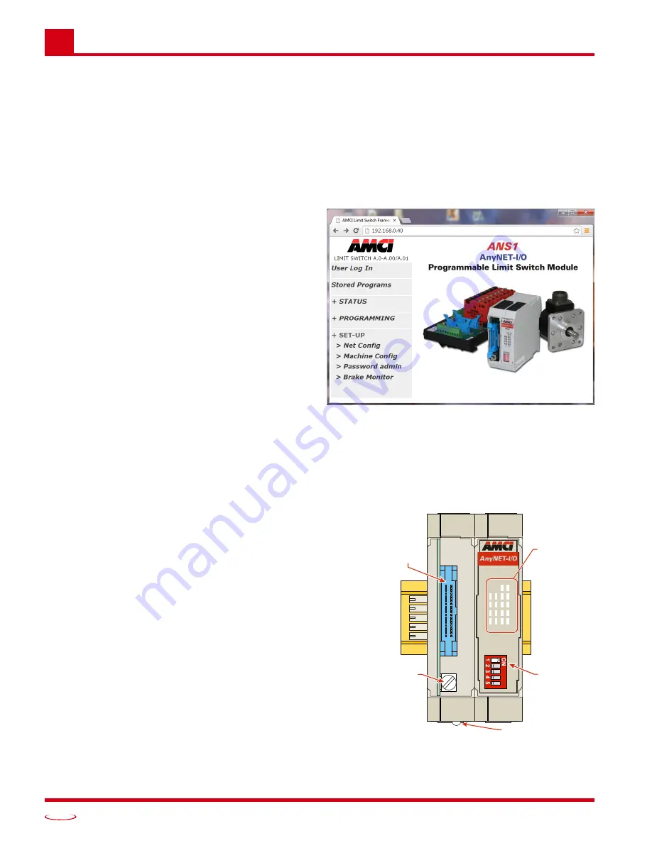
The ANS1 is the first AnyNET-I/O module to
include an integral web server, which allows
you to program the ANS1 from any web
browser. This allows you to run the ANS1 as
an independent product, without the need of a
host controller. If slaving multiple modules
together, each module has to be programmed
separately. The IP address of the web server is
programmable, so all of the modules can be
brought into one ethernet switch and pro-
grammed from one web browser connection.
Physical Description
Front Panel
Figure 1.3 shows the layout of the front panel. Compared
to most of the other AnyNET-I/O modules, the ANS1 is a
double width module. Even though it is twice the width, it
only takes one slot in the AnyNET-I/O stack.
Relay Board Connector. Allow the ANS1 to be con-
nected to AMCI RB-7 or RB-8 relay boards. These
relay boards give you access to all sixteen input and
output points. I/O on the relay board are numbered
1 through 8 when programming the ANS1.
Relay Cable Ground Lug. Use this point to ground
the shields on the relay board cable.
Stack Address DIP Switch. Used to set the address
of the ANS1 in an AnyNET-I/O Stack. If the ANS1
is used as the network host, then the module must
have an address of zero. (All switches off.)
Figure 1.2 ANS1 Web Interface
ADDRESS
PLS
PWR FUSE
IN OUT
09
09
13
13
10
10
14
14
11
11
15
15
12
12
16
16
Relay
Board
Connector
I/O Status
LED’s
Relay
Cable
Ground
Lug
Stack
Address
DIP Switch
Module Status LED
Figure 1.3 ANS1 Front Panel Callout
Summary of Contents for ANS1 ANYNET-I/O
Page 1: ...MICRO CONTROLS INC ADVANCED U s e r M anual Manual 940 0A090...
Page 6: ...Table of Contents ADVANCED MICRO CONTROLS INC 6 Notes...
Page 26: ...Limit Switch Functionality ADVANCED MICRO CONTROLS INC 2 26 Notes...
Page 36: ...Additional Functionality ADVANCED MICRO CONTROLS INC 3 36 Notes...
Page 90: ...LEADERS IN ADVANCED CONTROL PRODUCTS ADVANCED MICRO CONTROLS INC...


