Amada MAWA-300B-00-00 Operation Manual Download Page 133

MAWA-300B 

6. Timing Chart 

6-8 

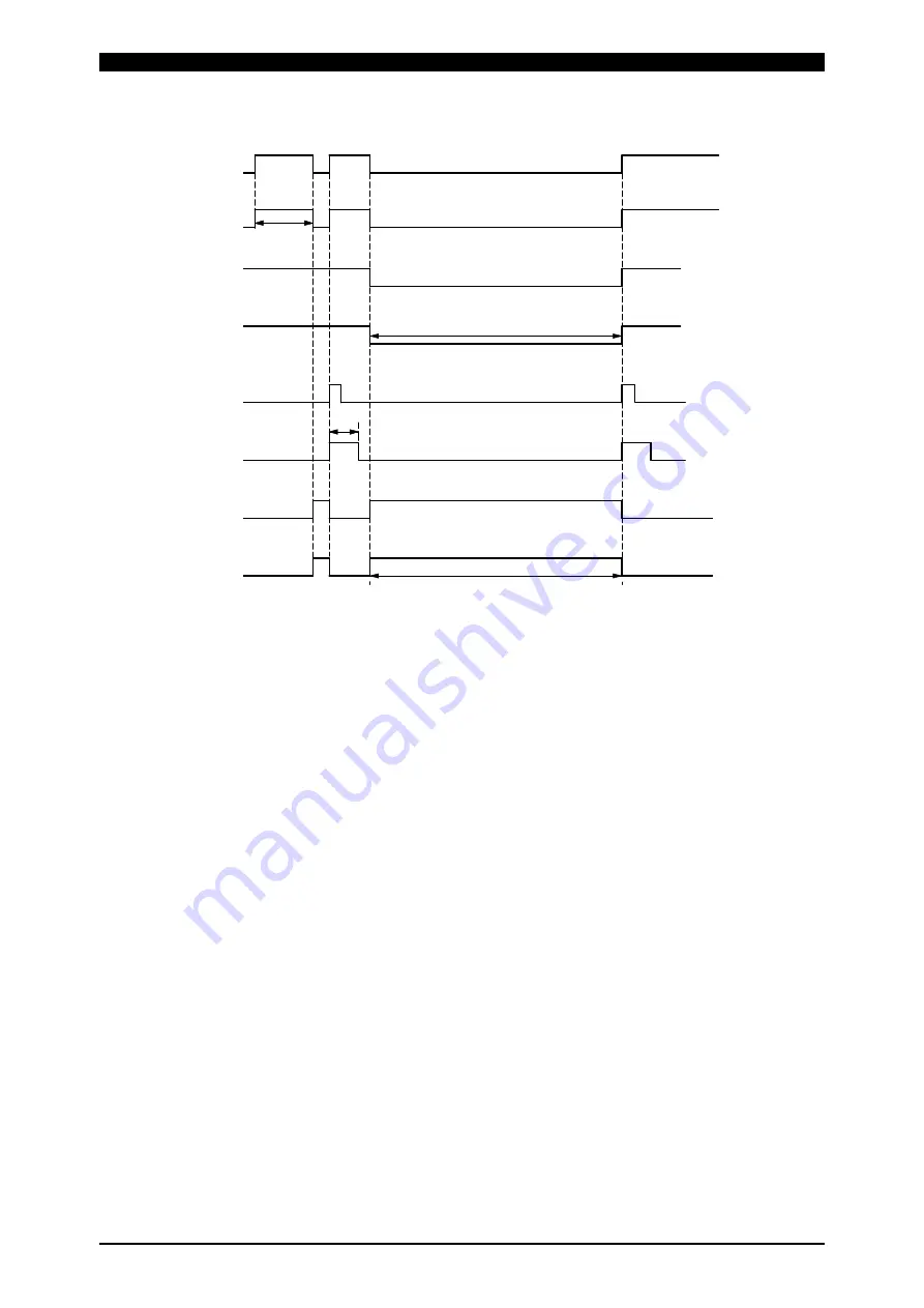
The following a timing chart for option input/output signals (M-READY, H-STOP and H-RESET). 
 

READY出力

通電開始可能状態

M-READY 出力

RESET 入力

H-ERROR入力

ERROR出力

H-RESET 出力

非常停止

H-STOP 出力

*1

*2

*3

*4


*1  The M-READY signal is output when 

MAWA-300B

 is ready for welding. 


*2 When 

MAWA-300B

 is in an emergency stop status, the H-STOP signal output is turned off.    (b contact)    The STOP signal is 

output after the emergency stop status is cleared. 


*3 When 

MAWA-300B

 receives the RESET input signal, it outputs the H-RESET output signal.    The H-RESET signal is output for 

the set time of “H-RESET signal output time.”     

Refer to “4. (6) Switch Select Screen.” 


*4 When 

MAWA-300B

 receives the H-ERROR signal, it outputs the ERROR signal, being put into an alarm status. 


READY output 

welding start enable status 

M-READY output 

Emergency stop 

H-STOP output 

RESET input 

H-RESET output 

H-ERROR input 

ERROR output 

Summary of Contents for MAWA-300B-00-00

Page 1: ...U12OM1190506 01 OPERATION MANUAL PULSETIG WELDING POWER SUPPLY MAWA 300B...

Page 2: ...3 3 1 Map of residual risks of the welding power supply unit 3 3 2 Map of residual risks of the standard system 4 4 Table of Residual Risks 5 4 1 Installation 5 4 2 Machine operation 7 4 3 Maintenance...

Page 3: ...or D Sub 37 pin female 2 24 3 2 2 Output connector D Sub 25 pin female 2 25 3 2 3 Option input output connector D Sub 25 pin male 2 26 3 3 External input output signal table 2 27 3 3 1 User input term...

Page 4: ...Supply 5 17 6 Timing Chart 1 Touch Start servo motor type welding head 6 1 2 Touch Start when the customer prepared motor head is used 6 2 3 Touch Start when the auto mode is set 6 3 4 Touch Start wh...

Page 5: ...MAWA 300B Contents iv 2 1 Monthly maintenance 9 3 2 1 1 Cleaning the cooling fan filter 9 3...

Page 6: ...Welfare issued in 2012 related to the promotion of notice of the risk or others on the machine by the transferor of the machine This chapter is a part of the operation manual Accordingly do not operat...

Page 7: ...ht shielding protector y Measures to be taken in an emergency y Prohibition of using the machine for other purposes than welding 1 3 Clothes for operations For executing welding operations put on clot...

Page 8: ...Welding power supply unit and welding power supply inside Electric shock Input terminal and output terminal Electric shock Input cable and connection cable Electric shock Output cable torch cable and...

Page 9: ...Poisoning Suffocation Respiratory trouble Wire supply unit Rolling in Fire Emergency stop button Main power switch Emergency stop button Electrode and torch Electric shock Gas generated from workpiece...

Page 10: ...chine strong arc light will be scattered at welding If this arc light is caught by eyes the eyes may be inflamed Protective measure Install a light shielding partition or light shielding curtain aroun...

Page 11: ...ied at a start of welding If a cable with an insufficient capacity or a cable with a low electric strength is used a fire or electric shock may be caused Protective measure Use the dedicated torch cab...

Page 12: ...the leather protective glasses for welding clothes with long sleeves foot cover and leather apron Do not allow any person thoughtlessly to enter an area around the welding machine and welding operati...

Page 13: ...ation place and the whole factory at all times Install sealed up equipment local exhaust device etc and put on a gas mask or dust proof mask as required 13 WARNING Welding Source of risk Electrode and...

Page 14: ...g jig Contents of risk Electrification is performed neat the welding jig If a person touches such a place an electric shock may occur Protective measure Perform grounding so as not to allow a workpiec...

Page 15: ...rode immediately after welding Contents of risk Immediately after welding the workpiece and electrode are still hot If the welded workpiece is touched with a bare hand or the electrode is touched in t...

Page 16: ...primary power wire on the factory side an electric shock may be caused by touching the charged part by mistake Protective measure Before performing inspection operations stop the electric power suppl...

Page 17: ...ntents of risk If the case is removed and the internal high voltage portion is touched immediately after the power supply is turned on or off this may result in a death Even after the power supply is...

Page 18: ...ource of risk Dust Contents of risk If dust is inhaled the human body may be badly affected Protective measure Classify collected dust according to materials and keep it in a can with a cover so that...

Page 19: ...n below Pasting place Upper part of the terminal cover Meaning Danger of electric shock CAUTION CONNECT GROUNDING WIRE DO NOT OPEN COVER TOUCHING THE INSIDE MAY CAUSE AN ELECTRIC SHOCK CAUTION CAUTION...

Page 20: ...ilized welding quality is realized by constant current control Noiseless performance and positioning of discharge can be achieved by the touch start type welding Each setting can be easily performed b...

Page 21: ...ting parts such as switches on the front panel are shown below For the function of each part refer to 3 1 Front Panel 1 Main power switch 2 Touch panel display 3 START button with a green LED incorpor...

Page 22: ...1 Welding power supply input terminal block 2 Input connector D Sub 37 pin female 3 Output connector D Sub 25 pin female 4 Optional input output connector D Sub 25 pin male 5 Current voltage monitor...

Page 23: ...ng method Air cooling fan motor Supply gas 2 Argon pressure 0 1 0 6 MPa flow rate 5 L min or more Any foreign substance water and oil must not come into piping Case protection IP21S Protection class I...

Page 24: ...full scale Setting range 30 300 A PEAK maximum value RMS effective value Upper limit Current monitor Lower limit 0 360 A Upper limit from the reference waveform Current envelope Lower limit from the r...

Page 25: ...Start prohibition START Welding start Established time 1 100 ms is settable RESET Error reset SCH1 2 4 8 16 32 64 Condition input PARITY Parity Function ON OFF is settable WELD STOP Welding interrupt...

Page 26: ...is dedicated to argon gas 3 This welding machine is classified as Class A in electromagnetic compatibility EMC based on CISPR11 The Class A equipment is intended for use in industrial environments and...

Page 27: ...MAWA 300B 1 Overview 1 8 3 2 Product dimensions 3 2 1 Main unit Unit mm 3 2 2 Panel unit Unit mm...

Page 28: ...f the total time of JIS C9300 1 3 37 is not adopted Also the duty cycle changes depending on the set time of the 1st welding the 2nd welding Example computation When weld time of the 1st welding the 2...

Page 29: ...OM1190505 OM1190506 1190935 1 D Sub connector 1 AS1184321 1184324 1 1 37 pin D Sub connector Emergency stop 1 input terminals 16 and 19 Emergency stop 2 input terminals 17 and 18 WELD ON input termina...

Page 30: ...6519 1156519 Cooling water circulator 3 WR 100 1173726 Flowmeter FR IIS P 1040773 Digital flow meter FSM2 NAF100 S06ARN P70 1188807 Input output signal cable 3 m 4 SK1187086 1187086 Torch stand MHT 50...

Page 31: ...e there is a high noise generating source in the neighborhood Where chemicals are handled Where it is very dusty Where there are lots of vibrations and shocks z Install the welding power supply in a s...

Page 32: ...ed below Take a serious view of the following contents Ambient temperature 5 40 C Maximum humidity 85 or less without condensation Maximum altitude 1000 m or lower Installing conditions Pollution leve...

Page 33: ...orch and torch mount must be 40 mm or greater z Do not use any gas other than argon gas to avoid an accidental fire z There is a solenoid valve inside of MAWA 300B to turn on off the argon gas At leas...

Page 34: ...a Flow rate 0 5 L min or more Reducing valve and flow meter Reference Manufacturer YUTAKA Co Ltd Product name 2 step pressure adjuster with a flow meter Model FR II S P Tube Recommended item Manufactu...

Page 35: ...t cable Put a cable cover on the contact portion with the moving part or human body so as not to damage the cable If a cable with a deteriorated or damaged cover is directly touched or if the metal pa...

Page 36: ...ocedure 1 Turn off the source power supply on the factory side 2 Pass the input cable through the cable gland lower of the terminal cover 3 Connect each of the round terminals of 3 power lines L1 L2 a...

Page 37: ...ith the moving part or human body so as not to damage the torch cable If a cable with a deteriorated or damaged cover is directly touched or if the metal part with which the cable is brought into cont...

Page 38: ...ections 2 8 2 Fix the end of the grounding cable to the grounding terminal with the attached bolts and nuts Remarks z When tightening the nut perform it so that the grounding cable may face toward the...

Page 39: ...on with the moving part or human body so as not to damage the torch cable If a cable with a deteriorated or damaged cover is directly touched or if the metal part with which the cable is brought into...

Page 40: ...torch cable and connect it to the torch terminal 3 Install the terminal cover on the rear panel Put the claws on the left and right side into the grooves of the rear panel 4 Fix the terminal cover wit...

Page 41: ...so that arc may not be scattered from the torch we prepare a torch with a meshed nozzle and a nozzle ring The nozzle ring is attached to our torch Install the nozzle ring on the nozzle and connect the...

Page 42: ...is used for the gas cylinder the gas cylinder may be exploded IMPORTANT z Use dry gas and connect the tube so as not to cause a foreign substance water and oil to flow into the piping In the following...

Page 43: ...side and control of external devices For connecting to external input output devices refer to 2 3 Interface 1 Input connector D Sub 37 pin female Used for control from the outside 2 Output connector D...

Page 44: ...ation device will be described There is a connector for external communication on the rear panel This connector is used to set conditions and read data from PC For the connection with the external com...

Page 45: ...d Remarks z The maximum rating for H CY VLV output signals is 24 V DC 70 mA or less Connection when the Torch drive type is set to MOTOR touch start head unit MH 109TA 25 13 3 8 17 16 12 7 9 6 4 2 1 1...

Page 46: ...t signal cable not to damage it z Do not use a deteriorated or damaged input output signal cable If a cable with a deteriorated or damaged cover is used malfunction or error may occur IMPORTANT z To a...

Page 47: ...r connected between panel unit and connector of the main unit 5 After re placing the front cover connect the input output signal cable between the connector on the rear panel of the panel unit and the...

Page 48: ...f the source power supply on the factory side 7 To install the panel unit with M4 taps 4 positions on both sides of the panel unit prepare metal fittings etc The length of screw put into M4 tap is 10...

Page 49: ...election signal can be detected by this terminal Perform a setting so that the total of condition selection signal lines and parity signal close circuits may be an odd number at all times Refer to SCH...

Page 50: ...nsor 0 V 25 24V Power supply for the gas flow rate sensor 24 V 35 EXT COM Input terminal common 36 INT 24V 24 V output 37 COM Input terminal common 1 For resetting emergency stop turn off both of EM1...

Page 51: ...rminals 1 5 and 7 11 7 OUT5 8 OUT4 9 OUT3 10 OUT2 11 OUT1 User output terminal For each terminal the following settings can be selected 01 GOOD 02 NG 03 END 04 ERROR 05 READY 06 LOST 07 WEL1 LOWER CUR...

Page 52: ...nd 3 7 Input 23 EXT_COM2 Common terminal of the input terminal 9 H OUT_COM Common terminal of the output terminals 10 14 10 H END End signal output terminal 11 H ORG Return to start point signal outpu...

Page 53: ...de and fine weld mode refer to 4 6 i and 5 6 2 3 1 4 Current voltage monitor connector D Sub 15 pin female Current voltage monitor Terminal No Terminal name Explanation 1 I Welding current analog sign...

Page 54: ...7 SCH16 8 SCH32 9 SCH64 10 PARITY 11 PURGE 12 RESET 22 IN1 23 IN2 16 EM1 17 EM2 21 WELD ON 24 0V Flow sensor 25 24V Flow sensor 18 EM2_COM EM2_COM EM2 EM1 IN2 IN1 RESET PURGE PARITY SCH64 SCH32 SCH16...

Page 55: ...6 18 WIRE START 12 SYNC OUT 9 OUT3 1 GOOD 2 NG 4 E STOP 7 OUT5 6 OUT_COM 3 END 8 OUT4 14 OUT_COM 5 ERROR 13 SYNC OUT_COM GOOD 17 WIRE START_COM 11 10 9 8 7 5 4 3 2 1 16 15 14 6 18 17 12 13 22 23 24 25...

Page 56: ...tion input output connector D Sub 25 pin male Option input output signals When the internal power supply is used connect terminal No 23 and terminal No 25 When the external power supply is used connec...

Page 57: ...erminal name Explanation 01 GAS FLOW When the optional gas flow sensor is connected E25 GAS FLOW ERROR occurs unless the sensor input is turned on at a gas purge 02 H ORG When the optional servo motor...

Page 58: ...for the 02 NG signal setting time 09 WEL1 LOWER VOLTAGE When the measured voltage value of the first welding is lower than the lower limit of judgment voltage value this signal is output for the 02 NG...

Page 59: ...LOPE CUR When the measured current waveform of the second welding is lower than the lower limit of the judgment current waveform this signal is output for the 02 NG signal setting time 24 WEL2 UPPER E...

Page 60: ...WELD STOP EM1 EM2 IN2 START 16 EM1 17 EM2 23 IN2 18 EM2_COM 19 EM1_COM 37 COM 35 EXT COM 1 WELD STOP 2 START Internal side External side 2 For connecting to the NPN open collector output when the int...

Page 61: ...1_COM 37 COM 35 EXT COM EM1 EM2 IN2 EM1_COM EM2_COM EXT COM START WELD STOP 1 WELD STOP 2 START Internal side External side 4 For connecting to the NPN open collector output device when the external p...

Page 62: ...is will result in a failure z Do not move the main power switch lever up within 3 seconds after power off If the main power switch lever is moved up immediately after power off the power is not suppli...

Page 63: ...ect screen welding is started by pressing this button while it lights 4 RESET button with an orange LED incorporated This button LED lights in orange when an alarm occurs The alarm will be cleared by...

Page 64: ...screen 15 Count setting screen 5 Basic setting screen 6 Switch select screen 8 Ext I O setting screen 9 Welding condition setting screen 10 Schedule setting screen 7 Initialize memory screen 11 Monito...

Page 65: ...nged over If the power supply is turned off before the screen is changed over the input set value becomes invalid z To go to a screen with the mark of when the password is effective Refer to 4 17 it i...

Page 66: ...tor screen Used to go to the Monitor screen b Basic setting Used to go to the Basic setting screen c Welding condition set Used to go to the Welding condition setting screen d Monitor select Used to g...

Page 67: ...power supply is turned on the Password input screen will not be displayed in going to the screen of after that It is possible to go to the screen without the password If Enter is pressed or the power...

Page 68: ...udgment or out of the envelope range the judgment results in NG Accidental fire LOST Lights in red When the initial current cannot be detected or a short circuit contact between a workpiece and the el...

Page 69: ...WELD1 welding range The WELD1 waveform is displayed in the center of the graph in a magnified form WELD 2 The waveform display can be selected within the WELD2 welding range The WELD2 waveform is disp...

Page 70: ...e weld time including the initial current section and cooling section is displayed 2 CURR RANGE A The display range of current waveform can be changed It can be selected among 60 A 180 A and 360 A 3 V...

Page 71: ...r to 4 11 c Slope time The initial current time and the cooling time are displayed at the reference waveform set on the Welding condition setting screen but the initial current time and the cooling ti...

Page 72: ...ld mode can be selected At this time the initial current time of the reference waveform on the monitor screen is displayed by adding the fixed time 500 ms Set conditions such as moving speed and movin...

Page 73: ...is displayed Normal GOOD Lights in green Error NG Lights in red When the monitor value is out of the upper lower limit judgment range the judgment result in NG Accidental fire LOST Lights in red When...

Page 74: ...r values of the WELD1 WELD2 welding voltage are displayed The unit is V The displayed value is PEAK maximum value or RMS effective value For selecting a display value refer to 4 6 d Measurement voltag...

Page 75: ...reen Refer to 2 Envelope setting screen are displayed The upper lower limit waveform is displayed in a dotted line Reference waveform Yellow solid line Current waveform Upper lower limit waveform Yell...

Page 76: ...event an overshoot waveform r Voltage The upper limit value and lower limit value to be used for voltage envelope judgment can be set as relative values for the first welding WELD1 and second welding...

Page 77: ...pe waveform data is saved into the condition No parameter being set u Envelope waveform registration status display It is displayed that the envelope waveform is registered in the condition No being s...

Page 78: ...ding power supplies are used enter 1 for the first unit 2 for the second unit and 3 for the third unit respectively These are used for recognition of device This device No can be set up to 31 Initial...

Page 79: ...ication at 19600 bps 38400 Performs communication at 38400 bps Initial value 9600 i Internal resistance It can be selected whether the resistor incorporated in MAWA 300B is used as a terminator for ex...

Page 80: ...his can select whether the PARITY input signal is included or not Refer to PARITY in 2 3 1 1 Input connector Initial value OFF c SCH Torch select by I O This can select whether the condition No and to...

Page 81: ...t At ON the fine weld mode is selected At OFF the auto mode is selected The fine weld mode auto mode is the special welding mode when the torch drive type is MOTOR and the initial current time FST is...

Page 82: ...s c END signal output time After the end of all the welding sequence the END signal output time can be set The setting range is 1 200 ms Initial value 200 ms d START signal input delay time Sets the t...

Page 83: ...time Touch start only The output time of the H END output signal can be set The setting range is 1 200 ms Initial value 200 ms g Op IO H RESET signal output time Touch start only The output time of t...

Page 84: ...d by pressing CLEAR in the Memory clear item on the Switch select screen 2 2 Yes Executes initialization Displays the Initializing memory screen during initialization No Goes back to the Switch settin...

Page 85: ...WEL2 UPPER CURRENT 19 WEL2 LOWER VOLTAGE 20 WEL2 UPPER VOLTAGE 21 WEL2 LOWER TIME 22 WEL2 UPPER TIME 23 WEL2 LOWER ENVELOPE CUR 24 WEL2 UPPER ENVELOPE CUR 25 WEL2 LOWER ENVELOPE VLT 26 WEL2 UPPER ENVE...

Page 86: ...ely FULL SETTING screen in which all the detail condition settings can be set by operator himself and SIMPLE SETTING screen in which conditions can be input easily 1 FULL SETTING screen a SCH No Selec...

Page 87: ...t the difference between the cooling time current and the set current of WELD2 to 250 A or less When the difference between the cooling time current and the set current of WELD2 is more than 250 A E11...

Page 88: ...ablish the set value For example when 100 5 ms is input the effective digits for 100 ms or more is 1 ms the set value is automatically corrected to 100 ms when the screen is switched from the Welding...

Page 89: ...1 127 Usually select No from 1 in order When the SCH Torch select by I O item of the Switch select screen 1 2 is set to OFF the condition No to be used for welding is equal to the condition No that is...

Page 90: ...condition No is displayed b Weld1 welding pulse modulation ON OFF Select whether to apply the pulse modulation to the first welding current Initial value OFF Waveform sample at pulse modulation OFF W...

Page 91: ...en the base current value is higher than the welding current value modulation is not performed The setting range is 15 300 A in unit of 1 A Initial value 15 A g Screen return switch The Welding condit...

Page 92: ...g range is 10 90 This setting is also applied to the pulse modulation of up slope and down slope Initial value 50 n Weld2 up down pulse modulation ON OFF Select whether to apply pulse modulation to th...

Page 93: ...ue of upper lower limit judgment can be set individually for WELD1 and WELD2 on the Upper lower limit set screen WELD1 WELD2 An upper lower limit judgment is performed in both ranges of WELD1 and WELD...

Page 94: ...oth acquisition of monitor value and upper lower limit judgment are performed only in the pulse current section WEL Initial value Exclude d Limit judgment output Set the item to make an upper lower li...

Page 95: ...econd welding WELD2 can be set The input range is 0 360 A Initial value Upper Limit 360 Lower Limit 0 A c Voltage Regarding the upper limit value and lower limit value to be used for upper lower limit...

Page 96: ...ed c Copy to Enter the condition No to copy the data of the condition No input in Copy from Copy source No Specify the copying range in the left right input field Example 1 To perform copying to condi...

Page 97: ...ata is displayed Items of WELD1 WELD2 data display area FST Initial current initial current time Touch start only UF1 UF2 Up slope initial current up slope time UL1 UL2 Up slope final current PL1 PL2...

Page 98: ...screen of 4 is displayed After the copy is normally terminated the SCH copy screen of 1 appears and the copy completion notice Copy finish is displayed k No No condition copy is performed and the SCH...

Page 99: ...l status is displayed Terminal 1 W STOP Terminal 9 SCH64 Terminal 2 START Terminal 10 PARITY Terminal 3 SCH1 Terminal 11 PURGE Terminal 4 SCH2 Terminal 12 RESET Terminal 5 SCH4 Terminal 13 EM RESET Te...

Page 100: ...optional servo motor type welding head or torch selector is used f Option input terminal state The input signal status is displayed Terminal 1 H ST1 Terminal 3 H READY Terminal 4 GAS Terminal 5 H T LO...

Page 101: ...rating switch Used to turn on off output signals For details refer to c Output signal operating switch of the I O check screen of 1 i Screen return switch The External I O check screen reappears j Scr...

Page 102: ...preset Work count Enabled when a value is input in Work count preset When Weld count value is equal to WELD count preset value the count is increased 1 and is displayed as Work count The setting range...

Page 103: ...l be deleted in order for updating a SCH The condition No at occurrence of an error is displayed If no error is found 0 is displayed b MESSAGE The error code and error message of each error that occur...

Page 104: ...invalidated b Regist The input password can be registered by pressing this switch after entering the password If the operator goes to a screen without pressing this switch the entered password will b...

Page 105: ...g the welding current to flow it can be set that the welding current output is turned on off a PURGE ON OFF The gas can be turned on and off by manual operation In 15 seconds after pressing this switc...

Page 106: ...ent voltage select RMS Enable START switch ON Internal Gas Flow ON High speed SCH change No Wave OFF Fine Weld Mode OFF Torch drive type 1 CYLINDER GOOD NG signal output time 200 ms END signal output...

Page 107: ...PRE time 0 ms FST time 1 0 0 ms UPS1 time 0 0 ms WEL1 time 0 0 ms DWS1 time 0 0 ms COL time 0 ms UPS2 time 0 0 ms WEL2 time 0 0 ms DWS2 time 0 0 ms Welding condition setting screen all of conditions N...

Page 108: ...WELD1 0 A Current value Lower limit value WELD2 0 A WELD1 50 00 V Upper limit value WELD2 50 00 V WELD1 0 00 V Voltage value Lower limit value WELD2 0 00 V WELD1 5000 ms Upper limit value WELD2 5000 m...

Page 109: ...ratus may be damaged IMPORTANT z Use the welding power supply without exceeding the maximum duty cycle Refer to 1 3 3 Duty cycle graph Using the welding power supply exceeding the maximum duty cycle w...

Page 110: ...pply on the factory side 2 Turn ON to the I side the Main power switch on the front panel The start up screen is displayed and then the Monitor screen is displayed on the touch panel display Monitor s...

Page 111: ...Basic setting screen y Device No y Communication type and communication speed y Display language selection y Screen brightness 1 Displaying the Basic setting screen 1 Press MENU in the upper right par...

Page 112: ...rks y The Switch select screen consists of 2 pages 1 Displaying the Switch select screen 1 Press on the Basic setting screen The Switch select screen 1 2 is displayed For the details of the Switch sel...

Page 113: ...n be set SIMPLE SETTING screen A small number of setting items can be set easily 1 Displaying the Welding condition setting screen 1 Press MENU in the upper right part of the screen The Menu screen is...

Page 114: ...g screen consists of 2 pages Schedule setting screen 1 2 The first welding pulse modulation can be set Schedule setting screen 2 2 The second welding pulse modulation can be set 1 Displaying the Sched...

Page 115: ...nto the welding conditions of different condition Nos Copy the welding conditions on the SCH copy screen 1 Displaying the SCH copy screen 1 Press MENU in the upper right of the screen The Menu screen...

Page 116: ...lower limit value Set the upper lower limit judging range and target items for the OK NG judgment on the Monitor select screen 1 Displaying the Monitor select screen 1 Press MENU in the upper right p...

Page 117: ...Upper lower limit set screen Remarks y For the upper lower limit value setting to be used for OK NG judgment using the envelope waveform refer to 4 4 2 Envelope setting screen 1 Displaying the Upper l...

Page 118: ...mode FST ms 0 Set time At the end of the initial current time after the head reaches the main welding position The welding setting waveform and the monitor waveform are displayed in the same time seri...

Page 119: ...e start position Start signal ON Head moves to workpiece surface from the standby position Pre flow Argon gas output ON After electrode and workpiece make contact torch follow up part moves up After t...

Page 120: ...Head is a standby state at the start position Start signal ON Head moves to workpiece surface from the standby position Pre flow Argon gas output ON After electrode and workpiece make contact torch fo...

Page 121: ...state at the start position Start signal ON Head moves to workpiece surface from the standby position Pre flow Argon gas output ON After electrode and workpiece make contact torch follow up part moves...

Page 122: ...obtain the optimum conditions Remarks y If the air type welding head is used when the touch start is selected the pre flow time is used as the head go down time Only when the Gas flow control item on...

Page 123: ...Remarks y When the Monitor screen is displayed welding is enabled and the READY signal is output 1 Displaying the Monitor screen 1 Press MONITOR in the upper right part of the screen The Monitor scre...

Page 124: ...check screen This screen permits checking the envelope waveform created by the welding waveform and upper lower limit value Envelope setting screen This screen permits selecting the reference waveform...

Page 125: ...9 Shutting off the Power Supply Shutting off the power supply will be described below 1 Set the Main power switch on the front panel to OFF The power supply is shut off 2 Turn off the source power su...

Page 126: ...en 7 If the pre flow set time is longer than the head weld point initial current arrival time the initial current is started after the lapse of the pre flow set time If shorter the initial current is...

Page 127: ...al 1 This timing chart is applicable to the case where when the customer prepared motor head is used the 3 positions of start point initial current point and main welding point are set for the head te...

Page 128: ...l Input GAS 1 200ms settable Head up start signal Output H HEAD UP Operation ready signal Output M READY READY 2 End signal Output H END END PULSETIG welding power supply MAWA 300B Welding power suppl...

Page 129: ...ignal Input H READY READY 1 Gas start signal Input GAS 1 200ms settable Head up start signal Output H HEAD UP Operation ready signal Output M READY READY 2 End signal Output H END END PULSETIG welding...

Page 130: ...et value of END signal output time Refer to 4 6 Switch Select Screen 4 Set value of GOOD NG signal output time Refer to 4 6 Switch Select Screen 5 The LOST signal is turned on concurrently with the ON...

Page 131: ...en the current flows when ENVELOPE in the Limit output judgment on the Monitor select screen is ON Refer to 4 11 Monitor Select Screen Remarks Connect the H CY VLV output signal Refer to 2 2 8 Connect...

Page 132: ...gnal input is not accepted The H ORG output signal is continuously output until the H READY signal is received 2 After MAWA 300B receives an H HEAD UP input signal it outputs an H HEAD UP output signa...

Page 133: ...off b contact The STOP signal is output after the emergency stop status is cleared 3 When MAWA 300B receives the RESET input signal it outputs the H RESET output signal The H RESET signal is output f...

Page 134: ...nd or later change Refer to 4 6 Switch Select Screen 3 Set value of END signal output time Refer to 4 6 Switch Select Screen 4 Set value of GOOD NG signal output time Refer to 4 6 Switch Select Screen...

Page 135: ...e of END signal output time Refer to 4 6 Switch Select Screen 4 Set value of GOOD NG signal output time Refer to 4 6 Switch Select Screen 5 It becomes about 1 3 s when the High speed SCH change No Wav...

Page 136: ...ms for the first condition change or approx 30 ms for the second or later change Refer to 4 6 Switch Select Screen 3 Set value of END signal output time Refer to 4 6 Switch Select Screen 4 Set value o...

Page 137: ...r change Refer to 4 6 Switch Select Screen 3 Set value of END signal output time Refer to 4 6 Switch Select Screen 4 Set value of GOOD NG signal output time Refer to 4 6 Switch Select Screen 5 The LOS...

Page 138: ...e minimum weld time 1 ms and about 340 ms at the maximum weld time 4 s From these contents the time from the end of SCH signal operation to READY signal ON becomes SCH changeover delay time 1 200 ms W...

Page 139: ...6 14 11 Schedule No and SCH Select Terminals Closed Blank Open Signal name SCH No SCH1 SCH2 SCH4 SCH8 SCH16 SCH32 SCH64 PARITY 1 2 3 4 5 6 7 8 9 10 11 12 13 14 15 16 17 18 19 20 21 22 23 24 25 26 27...

Page 140: ...MAWA 300B 6 Timing Chart 6 15 Signal name SCH No SCH1 SCH2 SCH4 SCH8 SCH16 SCH32 SCH64 PARITY 36 37 38 39 40 41 42 43 44 45 46 47 48 49 50 51 52 53 54 55 56 57 58 59 60 61 62 63 64 65 66 67 68 69 70...

Page 141: ...WA 300B 6 Timing Chart 6 16 Signal name SCH No SCH1 SCH2 SCH4 SCH8 SCH16 SCH32 SCH64 PARITY 71 72 73 74 75 76 77 78 79 80 81 82 83 84 85 86 87 88 89 90 91 92 93 94 95 96 97 98 99 100 101 102 103 104 1...

Page 142: ...17 118 119 120 121 122 123 124 125 126 127 Input signal ON A fault due to wire breakage of the condition select signal line can be detected by parity input signal Set this signal so that the total of...

Page 143: ...y communication and two way communication Communication speed Select one of the following speeds on the Basic setting screen 9600 14400 19200 and 38400 bps Data format Start bit 1 Data bit 8 Stop bit...

Page 144: ...cation mode perform setting so that multiple units may not transmit data at the same time Otherwise data collision will be caused to the communication line resulting in an abnormal operation y The RS...

Page 145: ...S10 D Torch No Fixed 2 digits of 01 02 E Welding result Fixed 2 digits of 01 03 01 GOOD 02 NG 03 LOST F WELD1 current Fixed 5 digits of 000 0 999 9 A G WELD1 voltage Fixed 5 digits of 00 00 99 99 V H...

Page 146: ...1 Error code 2 Fixed 2 digits of 01 25 F 1 Error code 3 Fixed 2 digits of 01 25 G 1 Error code 4 Fixed 2 digits of 01 25 H 1 Error code 5 Fixed 2 digits of 01 25 I 1 Error code 6 Fixed 2 digits of 01...

Page 147: ...lding is used for SH1 SH2 and SH3 2 Command No 07 is used fixedly for CC1 and CC2 3 When there is no error data the reply data is E00 Error reset Code Device No W Condition No S Command No Data Exampl...

Page 148: ...de Device No W Condition No S Command No Data Example The contents of data specified by Command 01 of Condition No 008 of the specified device No 01 are saved for one condition Host side I D 1 I D 2 W...

Page 149: ...nt 14 WELD2 down slope final current nnn 015 300 A in unit of 1 A 15 Pre flow time nnnn 0000 9999 ms 16 Initial current time nnn 000 999 ms 17 WELD1 up slope time 18 WELD1 main welding time 19 WELD1 d...

Page 150: ...current 7 WELD1 down slope final current 8 Cooling in process current value 9 WELD2 up slope initial current 10 WELD2 up slope final current 11 WELD2 main welding current 12 WELD2 down slope initial c...

Page 151: ...nnn 2 WELD1 current value lower limit nnn 000 360 A 3 WELD1 voltage value upper limit nn nn 4 WELD1 voltage value lower limit nn nn 00 00 50 00 V 5 WELD1 weld time upper limit nnnn 6 WELD1 weld time...

Page 152: ...value lower limit nnn 000 060 A 4 Envelope WELD1 voltage value upper limit nn nn 5 Envelope WELD1 voltage value lower limit nn nn 00 00 50 00 V 6 Envelope WELD2 current value upper limit nnn 7 Envelop...

Page 153: ...Language selection n 1 Japanese 2 English 3 Korean 4 Chinese simplified characters 5 German 10 Panel brightness adjustment nn 01 15 15 is the brightest 11 NG judgment error n 0 OFF 1 ON 12 Start pari...

Page 154: ...RENT 09 WEL1 LOWER VOLTAGE 10 WEL1 UPPER VOLTAGE 11 WEL1 LOWER TIME 12 WEL1 UPPER TIME 13 WEL1 LOWER ENVELOPE CUR 14 WEL1 UPPER ENVELOPE CUR 15 WEL1 LOWER ENVELOPE VLT 16 WEL1 UPPER ENVELOPE VLT 17 WE...

Page 155: ...Language selection n 1 Japanese 2 English 3 Korean 4 Chinese simplified characters 5 German 10 Panel brightness adjustment nn 01 15 15 is the brightest 11 NG judgment error n 0 OFF 1 ON 12 Start parit...

Page 156: ...2 WEL1 UPPER TIME 13 WEL1 LOWER ENVELOPE CUR 14 WEL1 UPPER ENVELOPE CUR 15 WEL1 LOWER ENVELOPE VLT 16 WEL1 UPPER ENVELOPE VLT 17 WEL2 LOWER CURRENT 18 WEL2 UPPER CURRENT 19 WEL2 LOWER VOLTAGE 20 WEL2...

Page 157: ...e 2 nn 01 28 3 Error code 3 nn 01 28 4 Error code 4 nn 01 28 5 Error code 5 nn 01 28 6 Error code 6 nn 01 28 7 Error code 7 nn 01 28 8 Error code 8 nn 01 28 Up to 8 error codes can be used When the nu...

Page 158: ...nts Character string Range 1 Welding result nn 01 GOOD 02 NG 03 LOST 2 WELD1 current nnn n 000 0 999 9 A 3 WELD1 voltage nn nn 00 00 99 99 V 4 WELD1 time nnnn n 0000 0 9999 0 ms 5 WELD2 current nnn n...

Page 159: ...a nnn 000 202 3 Current waveform data point 1 nnn n 000 0 300 0 A 204 Current waveform data point 202 Max nnn n 000 0 300 0 A Command 12 voltage waveform data check Common data Condition No 000 y Resi...

Page 160: ...ivisible by 22 22 s is rounded off the total number of data points may be different depending on the set time of WELD1 WELD2 Command 14 voltage waveform data acquisition Common data Condition No 000 y...

Page 161: ...n be made from the error status If the cause of the error is not removed the Error screen will be displayed again If an error display is disabled because communication with the touch panel display can...

Page 162: ...WELD NG ERROR The setting of NG judgment error is ON and the upper lower limit setting of each monitor was out of the range Immediately after welding Check that WELD the on the Monitor screen is ON C...

Page 163: ...H ST2 E18 START2 TIME UP ERROR When the initial current time is NOT set to 0 ms the main welding start input signal H ST2 is not turned on within the initial current time after the initial current st...

Page 164: ...R When the setting was made to an input terminal the gas flow was out of the allowable range set for the argon gas flow rate sensor at a gas flow operation At a start of welding Check the residual qua...

Page 165: ...ntinuously as bleep bleep bleep make contact with us z The START MODE CHECK screen is for checking the arc start type The START MODE CHECK screen is displayed after the main power switch is turned ON...

Page 166: ...damaged cable y Torch cable y Grounding cable y Input cable y Other connection cables Input output signal cable Data communication cable 1 2 Torch inspection Check the end of the torch for abrasion I...

Page 167: ...is displayed 3 Press PURGE OFF on the Maintenance screen PURGE ON is displayed and argon gas flows for about 15 seconds After the argon gas flow is stopped PURGE OFF is automatically displayed again I...

Page 168: ...ooling fan filter for dirt once a month If the cooling fan filter is dirty clean it according to the following procedure 1 Loosen the thumb screw fixing the cooling fan filter and then remove it from...

Reviews: